Paolo
Well-Known Member
- First Name
- Paolo
- Joined
- Oct 18, 2019
- Threads
- 28
- Messages
- 728
- Reaction score
- 691
- Location
- Smallest continent in the world!
- Car(s)
- 20 SUPRA
- Thread starter
- #1
Not sure if this has been posted, but its a great read for those curious about the A90's suspension setup.
Enjoy.
2020 Toyota GR Supra Suspension Deep Dive
How Toyota put together all those BMW bits and pieces
Dan Edmunds
Mar 18th 2020 at 12:00PM

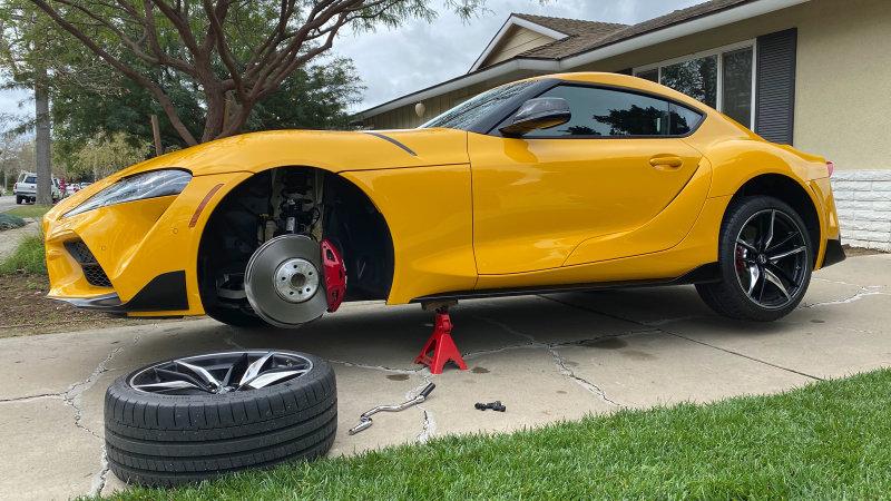
The new 2020 Toyota Supra is amazing, and by now its bold styling has begun to grow on me. It helps that the first one I drove proved to be an absolute blast on a tight and technical circuit, and this yellow example I’ve got now shows it to be a pleasant and compliant daily driver –– even on some pretty terrible broken concrete roads in my Southern California neighborhood.
Much of this, of course, has to do with the underlying BMW-ness of this car, which rides on a shared platform and is built at the same Austrian plant that assembles the BMW Z4 convertible. That said, Toyota deserves a lot of credit for solid choices when it comes to the Supra’s distinct suspension tuning.
Such variables as spring rates, damping force curves, steering effort mapping and bushing rates are invisible to the naked eye. But these factors will differ, not only because the Supra is lighter and has a fixed roof, but also because Toyota and BMW have different corporate priorities when it comes to ride and handling. We won’t see such calibration differences in the images that follow, but we will get to ogle the basic suspension architecture they both share.

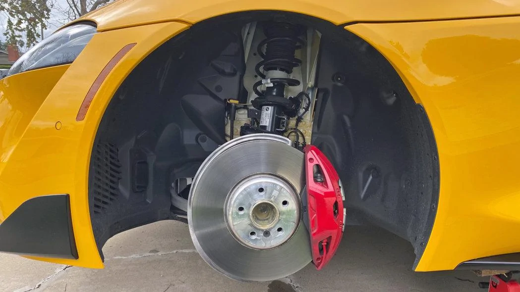
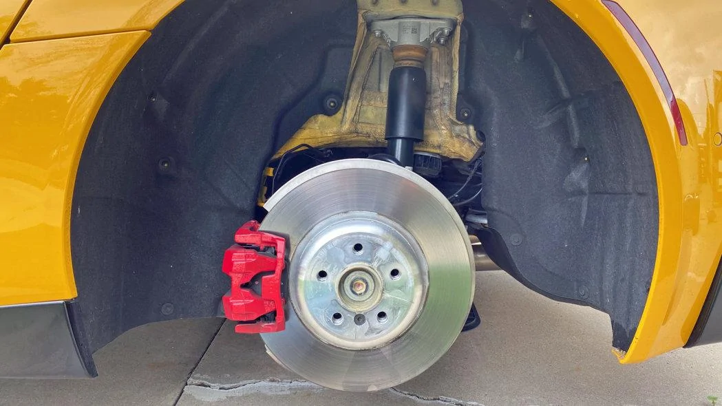
It’s obvious from here that the Supra uses a strut-type front suspension and has decent-sized four-piston fixed brake calipers. The other takeaway has to do with BMW’s strong influence, which is apparent in the use of wheel lug bolts instead of Toyota’s usual recipe of lug studs and lug nuts. And the BMW logos, of course. We’ll be seeing lots of those.
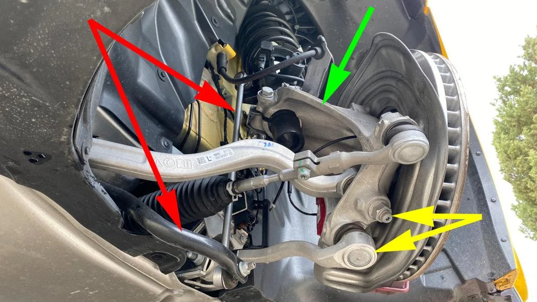
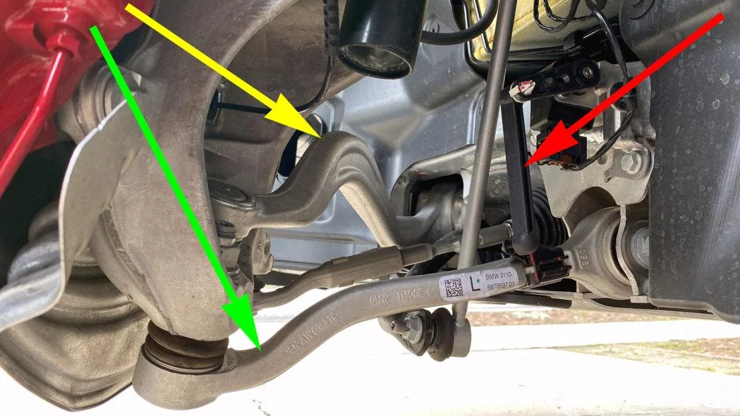
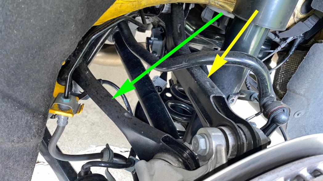
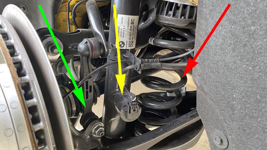
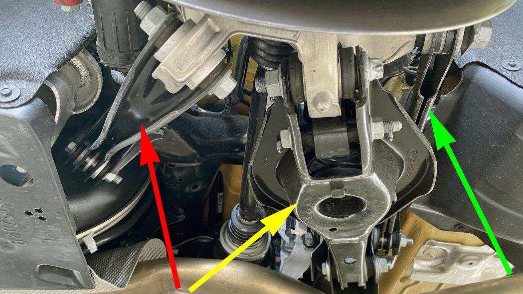
Aluminum has been used extensively to reduce the front suspension’s mass, the main exception being the stabilizer bar (red) and the long link that connects it to the strut housing. The large hub carrier (green) is an especially nice-looking aluminum piece. But let’s ignore that for a moment and zero in on the dual pivot arrangement (yellow) that employs two lower links instead of a wishbone.
A dual pivot arrangement is beneficial because it pushes the lower steering pivot point outward. The intersection of these two lines defines a virtual pivot point that, despite the distortion in this photo, lies somewhere within the brake rotor’s cooling vanes. Such a thing would be impossible with an A-shaped wishbone with a single ball joint.
This has two benefits: it reduces the scrub radius by pushing the pivot axis closer to the center of the tire’s contact patch, and it increases the inclination of the steering pivot axis –– an imaginary line that extends upward from here to the top of the strut. But that’s the mechanics. The payoff is an improvement in the steering’s natural self-centering and straight tracking.
The two links also have separate duties. The rearmost one (green) is square to the chassis and resists lateral loads, while the forward one (yellow) angles toward the front to locate the wheel in the fore-aft direction. The two steering pivots can’t stand too far apart, which is why one comes down from the top and the other up from the bottom. The forward one’s upper mounting clears the way for the steering linkage to pass underneath, but that big upward bend is a bit of a puzzle.
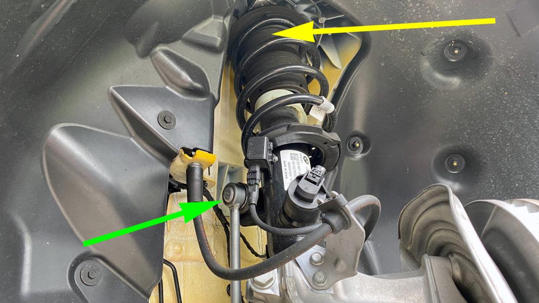
Meanwhile, off to the side, a height sensor (red) monitors the suspension’s position. All four corners of the car have one, and this data is used by the car’s variable damper system.
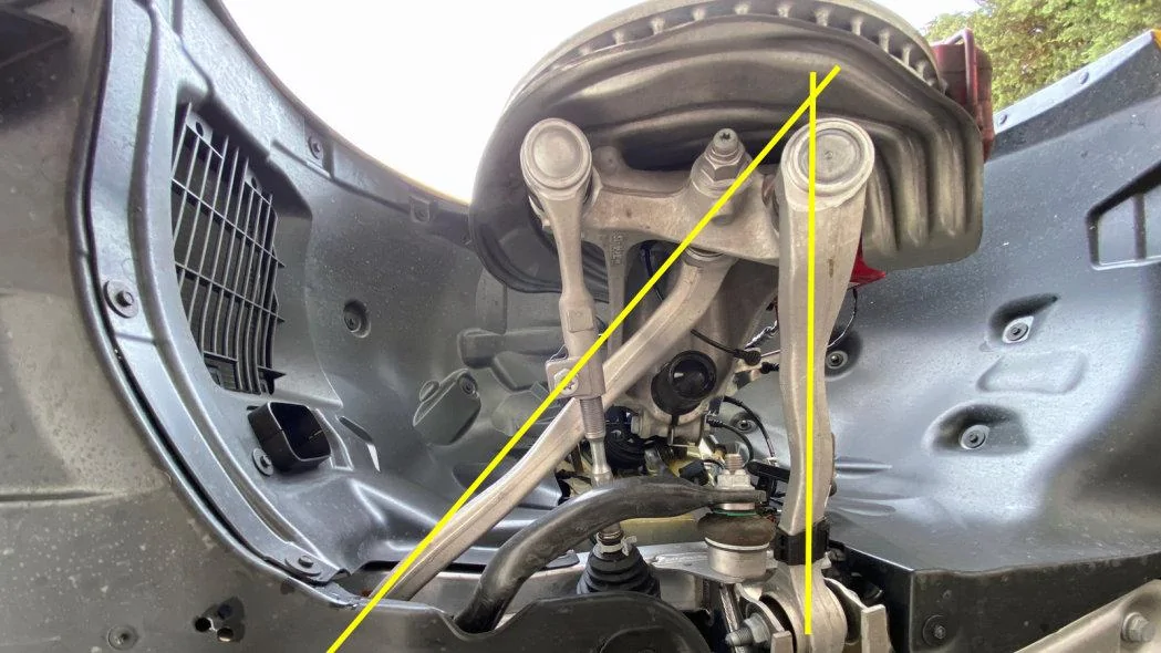
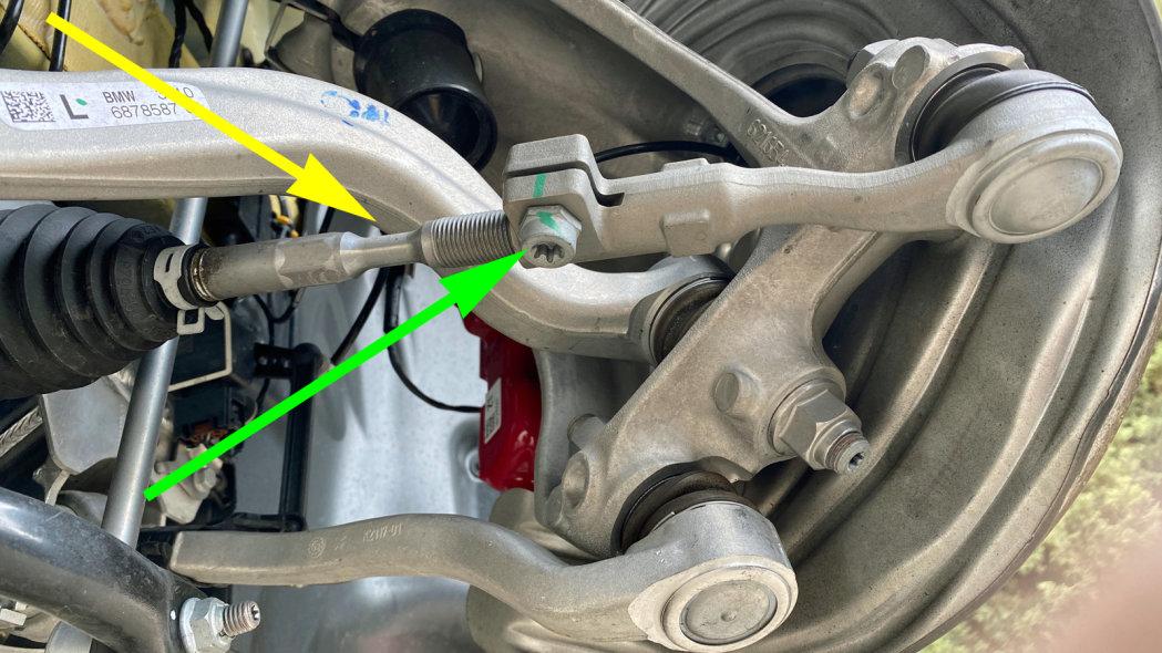
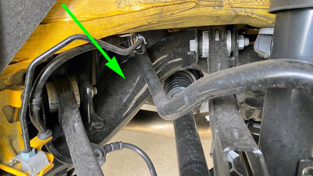
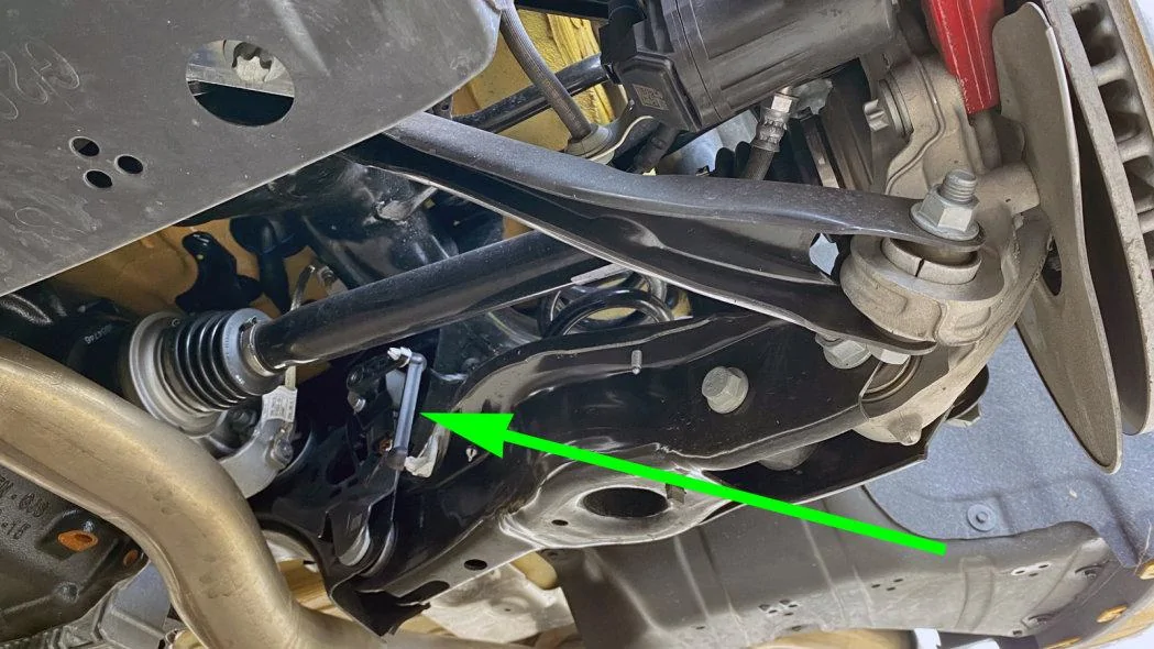
The excess space beneath the curved link is something that happens at full right lock, but it all but disappears at full left lock. They even necked down the steering link (yellow) for a little extra insurance. Incidentally, I do like the use of a pinch joint (green) instead of a clumsy jam nut to loosen the link to make a toe change.
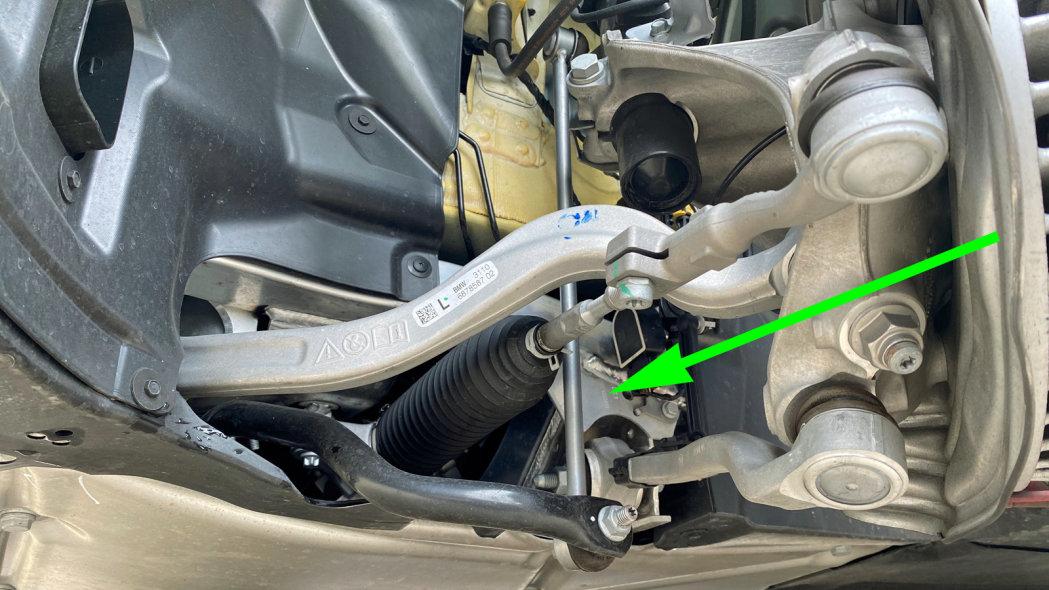
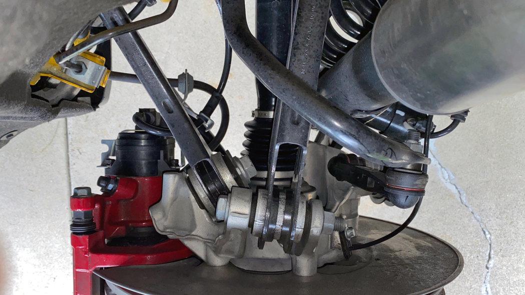
It’s all very tidy and neat. The thing to notice here is the inner pivot attachment point (green) of the lower lateral link. It connects to an aluminum front subframe.
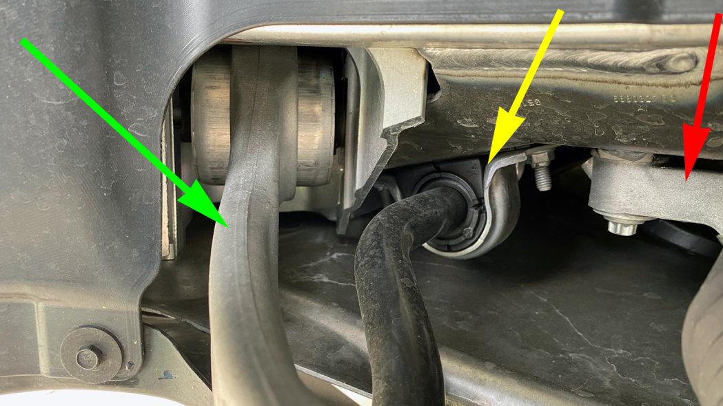
Further forward, the aluminum subframe has attachment points for the steering rack (red), the stabilizer bar pivot bushing (yellow) and the forward lower link (green.) The use of aluminum subframe doesn’t reduce unsprung mass, but it does reduce overall front mass. This was a big factor in getting the Supra’s weight distribution down to 50/50 –– no mean feat in a front-engined car.
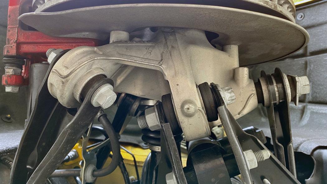
As with any strut suspension, the entire spring/damper assembly pivots when you turn the wheel, with the upper end of the steering pivot axis (yellow) up where the strut mounts to the body. The long stabilizer bar connecting link (green) connects to the strut housing in a position that allows it to follow the turning motion of the strut without contacting anything.
As with most strut setups, the front bump stop is hidden inside the dust boot.
The Supra uses electronically-controlled dampers made by Monroe that are marketed as Continuously Variable Semi-Active Suspension with external valve technology (CVSAe). These are twin-tube dampers with an electronically controlled bypass valve (yellow) that can soften the dampers (or not) over a continuous range of incremental steps every hundredth of a second.
A computer decides what to do based on data from the height sensors, a steering sensor, three g sensors and the driver’s sport/comfort mode selection. The hardware and software will have been tuned in a joint effort by Monroe and Toyota to get the performance they want. BMW will almost certainly have tuned the software differently for the Z4.
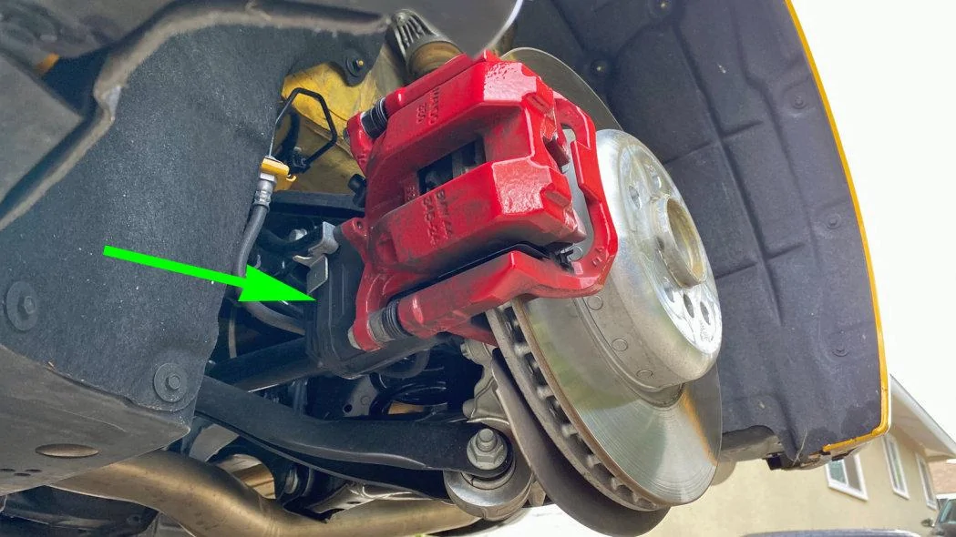
The Supra’s four-piston fixed front calipers use an open window design that makes it easy to access the brake pads by extracting two slender pins (yellow). But I must say I’ve never before seen mass dampers — those silver hunks on the corners — that large on a set of brake pads.
Moving to the rear, the brake rotor obscures everything except the single-piston sliding brake caliper and the bump stop at the top of the rear shock mount.
A closer look shows a multi-link rear suspension, but we can’t tell what kind just yet. This pair of top links closely approximates an upper wishbone, with the rear one (yellow) slightly more square with the chassis to brace the wheel’s upper end laterally and an angled forward one (green) to help define the fore-aft position.
The same two links, but the view is straight down from the top this time. They both connect to an aluminum hub carrier, but they’re stacked one atop the other so the forward link can have a nice angle to it.
The pivot points of our two upper links attach to a steel rear subframe (green). With 50/50 balance being the main goal, going to great lengths to save weight back here might have been counterproductive. Also, the powertrain is feeding a lot of torque through the rear end. It’s important to have a robust platform, especially if a high-output version enters the picture in the next year or two.
The rear stabilizer bar’s end link (green) connects directly to the aluminum hub carrier, which gives the bar 1-to-1 motion ratio relative to vertical wheel motion. Further inboard there’s a Monroe CVSAe damper and its electronically-controlled bypass valve (yellow), and inside of that the spring (red) is sandwiched between the body and a lower link we can’t quite make out.
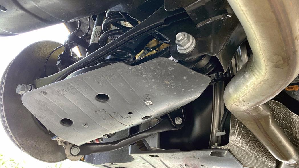
That plastic aero undercover is in the way. It’ll have to come off.
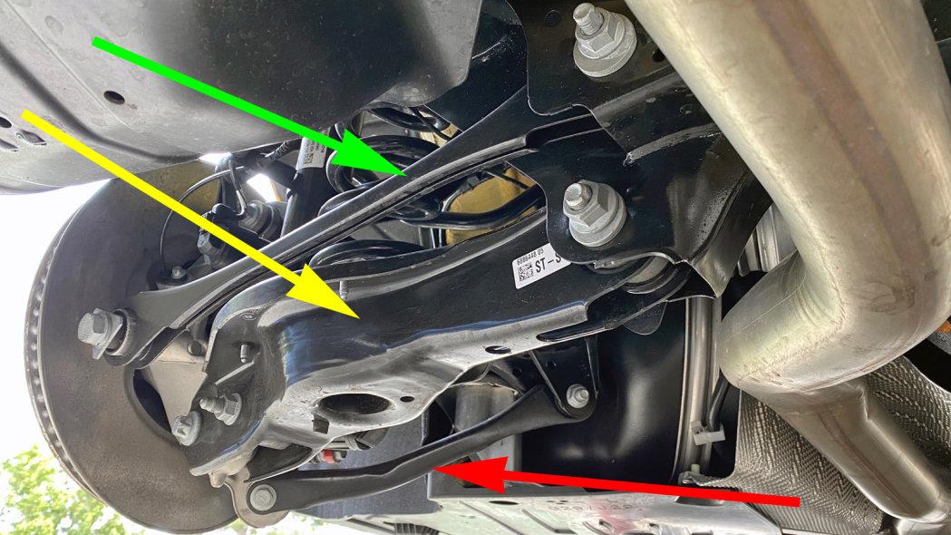
At last. This is a classic multi-link setup, which is to say it uses five discrete links. In addition to the two above, we see three more below. The forwardmost is an angled lower link (red) that is parallel to its partner up top. You couldn’t see it in the earlier top-down image because it was lined up exactly underneath.
It’s paired with a massive lateral lower link (yellow) that has to be beefy because it supports the weight of the car due to its status as the lower mounting point for the spring and shock absorber. It’s doing a lot more than a normal link, so I’ll go ahead and call it a control arm. The eccentric on its inner end is where you’d adjust the rear wheel’s camber.
The slender link higher up (green) is the toe link that keeps the rear wheel pointing straight ahead, and it has an eccentric to set static toe. It is longer than the lower control arm, not to mention higher and farther back, which means it is designed to create dynamic toe-in on the outside tire as the car heels over in corners –– a good trait to stave off roll-induced oversteer.
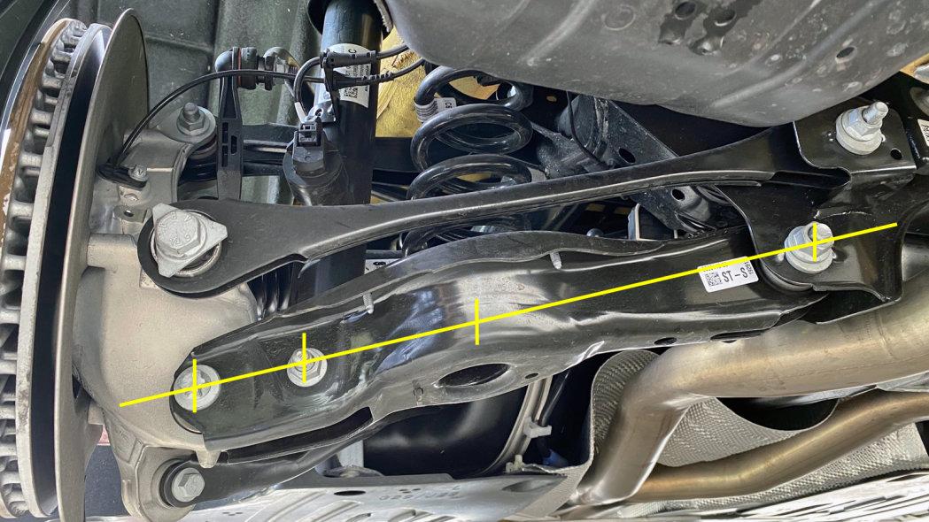
The spring’s position is just past the midway point between the lower link’s endpoints, which gives it a motion ratio of about 0.55-to-1. The spring will compress 0.55 inches for every inch of wheel travel, so the spring rate has to be proportionally stiffer to achieve a desired wheel rate.
The shock is mounted farther out at what looks like 80 percent of the length of the link, which gives it a more efficient motion ratio of 0.8-to-1 or so. Nothing about any of this is bad, but such things have to be taken into account when choosing spring rates and damping levels.
This view shows how the forward (red) and lateral (yellow) lower links form a rough triangle, much like their partners up top. Together the four of them brace the wheel’s position fore and aft, in acceleration and brake torque, and define the camber angle as if they were a stacked pair of wishbones. The toe link (green) merely keeps the wheel pointed straight ahead.
The only aluminum bit of consequence is the rear hub carrier, but that’s pretty consequential because 100 percent of that is unsprung mass. As a rule, only 50 percent of any link, spring or damper gets counted as unsprung mass because just one end moves while the other is fixed. Meanwhile, we can finally see the rear height sensor (green).
The two lower link attachments surround the hub carrier lobes in an arrangement called double shear. The toe link, on the other hand, can get away with a simpler single shear mount because it’s not loaded that much.
The rear brake is a single-piston sliding caliper with an electronic parking brake actuator (green) bolted onto the back. The rotors are nicely vented and, like the front, these are composite two-piece rotors that have a cast iron friction surface that’s riveted to an aluminum hub to improve heat dissipation while reducing unsprung mass and rotational inertia.
Toyota didn’t go nuts on the wheel and tire sizing, but it pays off in reasonable wheel assembly weights. The fronts are 255/35ZR19 tires mounted on 9x19-inch wheels, and the combination weighs 47.5 pounds. Out back they use 275/35ZR19 tires and 10x19-inch wheels that weigh 52.5 pounds mounted and ready to go. The Z4 uses the same Michelin Pilot Super Sport tires, but different wheels. Your mass may vary.
And that’s likely to be true of a lot of aspects of the two cars. A BMW Z4 will certainly look very much the same underneath, but the fundamental structural and mass differences that separate any related coupe and convertible will by themselves lead to suspension tuning differences. Now layer onto that the differing philosophies of the two companies that sell them. Even though the various pieces may well bolt up, methinks it wouldn’t be a great idea to rebuild a wrecked Supra with Z4 parts, and vice versa.
Contributing writer Dan Edmunds is a veteran automotive engineer and journalist. He worked as a vehicle development engineer for Toyota and Hyundai with an emphasis on chassis tuning, and was the director of vehicle testing at Edmunds.com (no relation) for 14 years.
https://www.autoblog.com/2020/03/18/toyota-supra-suspension-deep-dive/
Enjoy.
2020 Toyota GR Supra Suspension Deep Dive
How Toyota put together all those BMW bits and pieces
Dan Edmunds
Mar 18th 2020 at 12:00PM
The new 2020 Toyota Supra is amazing, and by now its bold styling has begun to grow on me. It helps that the first one I drove proved to be an absolute blast on a tight and technical circuit, and this yellow example I’ve got now shows it to be a pleasant and compliant daily driver –– even on some pretty terrible broken concrete roads in my Southern California neighborhood.
Much of this, of course, has to do with the underlying BMW-ness of this car, which rides on a shared platform and is built at the same Austrian plant that assembles the BMW Z4 convertible. That said, Toyota deserves a lot of credit for solid choices when it comes to the Supra’s distinct suspension tuning.
Such variables as spring rates, damping force curves, steering effort mapping and bushing rates are invisible to the naked eye. But these factors will differ, not only because the Supra is lighter and has a fixed roof, but also because Toyota and BMW have different corporate priorities when it comes to ride and handling. We won’t see such calibration differences in the images that follow, but we will get to ogle the basic suspension architecture they both share.
It’s obvious from here that the Supra uses a strut-type front suspension and has decent-sized four-piston fixed brake calipers. The other takeaway has to do with BMW’s strong influence, which is apparent in the use of wheel lug bolts instead of Toyota’s usual recipe of lug studs and lug nuts. And the BMW logos, of course. We’ll be seeing lots of those.
Aluminum has been used extensively to reduce the front suspension’s mass, the main exception being the stabilizer bar (red) and the long link that connects it to the strut housing. The large hub carrier (green) is an especially nice-looking aluminum piece. But let’s ignore that for a moment and zero in on the dual pivot arrangement (yellow) that employs two lower links instead of a wishbone.
A dual pivot arrangement is beneficial because it pushes the lower steering pivot point outward. The intersection of these two lines defines a virtual pivot point that, despite the distortion in this photo, lies somewhere within the brake rotor’s cooling vanes. Such a thing would be impossible with an A-shaped wishbone with a single ball joint.
This has two benefits: it reduces the scrub radius by pushing the pivot axis closer to the center of the tire’s contact patch, and it increases the inclination of the steering pivot axis –– an imaginary line that extends upward from here to the top of the strut. But that’s the mechanics. The payoff is an improvement in the steering’s natural self-centering and straight tracking.
The two links also have separate duties. The rearmost one (green) is square to the chassis and resists lateral loads, while the forward one (yellow) angles toward the front to locate the wheel in the fore-aft direction. The two steering pivots can’t stand too far apart, which is why one comes down from the top and the other up from the bottom. The forward one’s upper mounting clears the way for the steering linkage to pass underneath, but that big upward bend is a bit of a puzzle.
Meanwhile, off to the side, a height sensor (red) monitors the suspension’s position. All four corners of the car have one, and this data is used by the car’s variable damper system.
The excess space beneath the curved link is something that happens at full right lock, but it all but disappears at full left lock. They even necked down the steering link (yellow) for a little extra insurance. Incidentally, I do like the use of a pinch joint (green) instead of a clumsy jam nut to loosen the link to make a toe change.
It’s all very tidy and neat. The thing to notice here is the inner pivot attachment point (green) of the lower lateral link. It connects to an aluminum front subframe.
Further forward, the aluminum subframe has attachment points for the steering rack (red), the stabilizer bar pivot bushing (yellow) and the forward lower link (green.) The use of aluminum subframe doesn’t reduce unsprung mass, but it does reduce overall front mass. This was a big factor in getting the Supra’s weight distribution down to 50/50 –– no mean feat in a front-engined car.
As with any strut suspension, the entire spring/damper assembly pivots when you turn the wheel, with the upper end of the steering pivot axis (yellow) up where the strut mounts to the body. The long stabilizer bar connecting link (green) connects to the strut housing in a position that allows it to follow the turning motion of the strut without contacting anything.
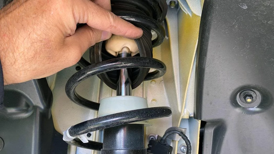
As with most strut setups, the front bump stop is hidden inside the dust boot.
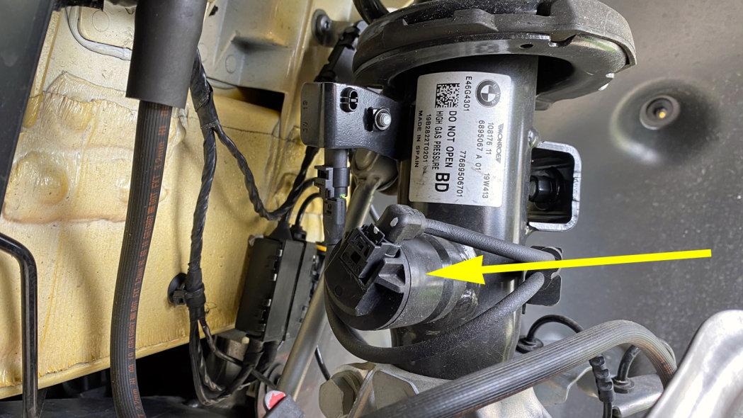
The Supra uses electronically-controlled dampers made by Monroe that are marketed as Continuously Variable Semi-Active Suspension with external valve technology (CVSAe). These are twin-tube dampers with an electronically controlled bypass valve (yellow) that can soften the dampers (or not) over a continuous range of incremental steps every hundredth of a second.
A computer decides what to do based on data from the height sensors, a steering sensor, three g sensors and the driver’s sport/comfort mode selection. The hardware and software will have been tuned in a joint effort by Monroe and Toyota to get the performance they want. BMW will almost certainly have tuned the software differently for the Z4.
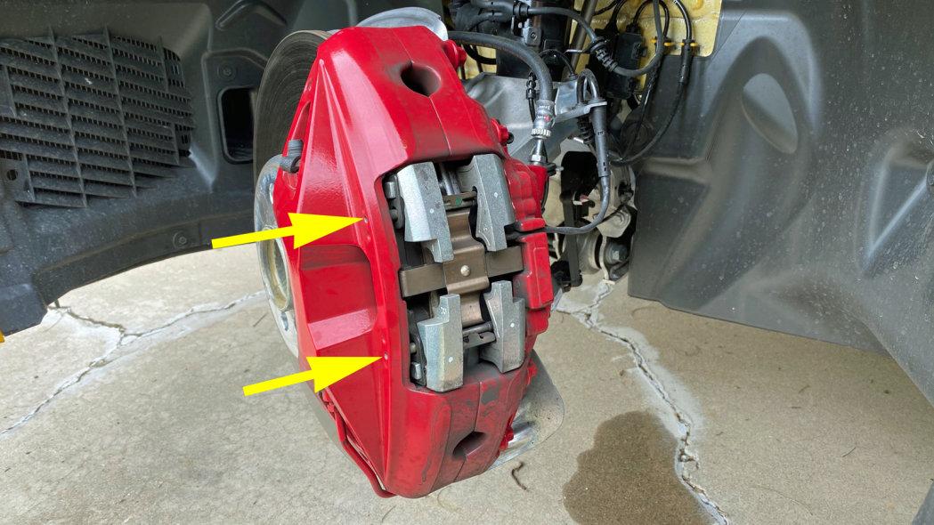
The Supra’s four-piston fixed front calipers use an open window design that makes it easy to access the brake pads by extracting two slender pins (yellow). But I must say I’ve never before seen mass dampers — those silver hunks on the corners — that large on a set of brake pads.
Moving to the rear, the brake rotor obscures everything except the single-piston sliding brake caliper and the bump stop at the top of the rear shock mount.
A closer look shows a multi-link rear suspension, but we can’t tell what kind just yet. This pair of top links closely approximates an upper wishbone, with the rear one (yellow) slightly more square with the chassis to brace the wheel’s upper end laterally and an angled forward one (green) to help define the fore-aft position.
The same two links, but the view is straight down from the top this time. They both connect to an aluminum hub carrier, but they’re stacked one atop the other so the forward link can have a nice angle to it.
The pivot points of our two upper links attach to a steel rear subframe (green). With 50/50 balance being the main goal, going to great lengths to save weight back here might have been counterproductive. Also, the powertrain is feeding a lot of torque through the rear end. It’s important to have a robust platform, especially if a high-output version enters the picture in the next year or two.
The rear stabilizer bar’s end link (green) connects directly to the aluminum hub carrier, which gives the bar 1-to-1 motion ratio relative to vertical wheel motion. Further inboard there’s a Monroe CVSAe damper and its electronically-controlled bypass valve (yellow), and inside of that the spring (red) is sandwiched between the body and a lower link we can’t quite make out.
That plastic aero undercover is in the way. It’ll have to come off.
At last. This is a classic multi-link setup, which is to say it uses five discrete links. In addition to the two above, we see three more below. The forwardmost is an angled lower link (red) that is parallel to its partner up top. You couldn’t see it in the earlier top-down image because it was lined up exactly underneath.
It’s paired with a massive lateral lower link (yellow) that has to be beefy because it supports the weight of the car due to its status as the lower mounting point for the spring and shock absorber. It’s doing a lot more than a normal link, so I’ll go ahead and call it a control arm. The eccentric on its inner end is where you’d adjust the rear wheel’s camber.
The slender link higher up (green) is the toe link that keeps the rear wheel pointing straight ahead, and it has an eccentric to set static toe. It is longer than the lower control arm, not to mention higher and farther back, which means it is designed to create dynamic toe-in on the outside tire as the car heels over in corners –– a good trait to stave off roll-induced oversteer.
The spring’s position is just past the midway point between the lower link’s endpoints, which gives it a motion ratio of about 0.55-to-1. The spring will compress 0.55 inches for every inch of wheel travel, so the spring rate has to be proportionally stiffer to achieve a desired wheel rate.
The shock is mounted farther out at what looks like 80 percent of the length of the link, which gives it a more efficient motion ratio of 0.8-to-1 or so. Nothing about any of this is bad, but such things have to be taken into account when choosing spring rates and damping levels.
This view shows how the forward (red) and lateral (yellow) lower links form a rough triangle, much like their partners up top. Together the four of them brace the wheel’s position fore and aft, in acceleration and brake torque, and define the camber angle as if they were a stacked pair of wishbones. The toe link (green) merely keeps the wheel pointed straight ahead.
The only aluminum bit of consequence is the rear hub carrier, but that’s pretty consequential because 100 percent of that is unsprung mass. As a rule, only 50 percent of any link, spring or damper gets counted as unsprung mass because just one end moves while the other is fixed. Meanwhile, we can finally see the rear height sensor (green).
The two lower link attachments surround the hub carrier lobes in an arrangement called double shear. The toe link, on the other hand, can get away with a simpler single shear mount because it’s not loaded that much.
The rear brake is a single-piston sliding caliper with an electronic parking brake actuator (green) bolted onto the back. The rotors are nicely vented and, like the front, these are composite two-piece rotors that have a cast iron friction surface that’s riveted to an aluminum hub to improve heat dissipation while reducing unsprung mass and rotational inertia.
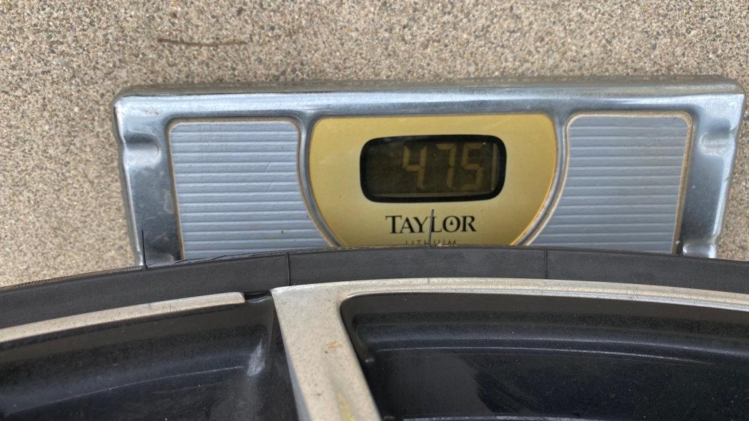
Toyota didn’t go nuts on the wheel and tire sizing, but it pays off in reasonable wheel assembly weights. The fronts are 255/35ZR19 tires mounted on 9x19-inch wheels, and the combination weighs 47.5 pounds. Out back they use 275/35ZR19 tires and 10x19-inch wheels that weigh 52.5 pounds mounted and ready to go. The Z4 uses the same Michelin Pilot Super Sport tires, but different wheels. Your mass may vary.
And that’s likely to be true of a lot of aspects of the two cars. A BMW Z4 will certainly look very much the same underneath, but the fundamental structural and mass differences that separate any related coupe and convertible will by themselves lead to suspension tuning differences. Now layer onto that the differing philosophies of the two companies that sell them. Even though the various pieces may well bolt up, methinks it wouldn’t be a great idea to rebuild a wrecked Supra with Z4 parts, and vice versa.
Contributing writer Dan Edmunds is a veteran automotive engineer and journalist. He worked as a vehicle development engineer for Toyota and Hyundai with an emphasis on chassis tuning, and was the director of vehicle testing at Edmunds.com (no relation) for 14 years.
https://www.autoblog.com/2020/03/18/toyota-supra-suspension-deep-dive/
Sponsored
