What did you do to your Supra today?
- Thread starter Ryanthetemp
- Start date
- Watchers 569
lucky phil
Well-Known Member
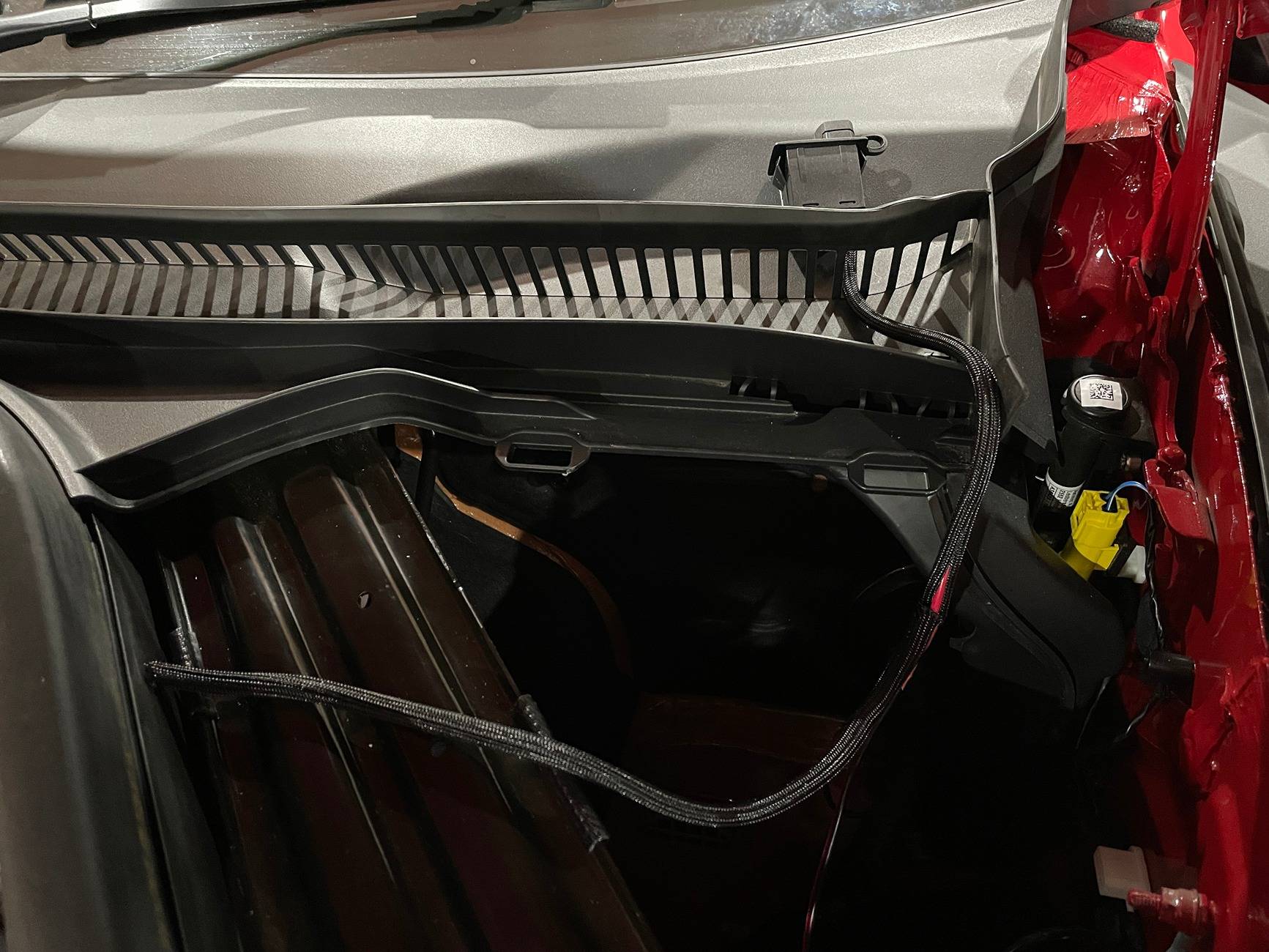
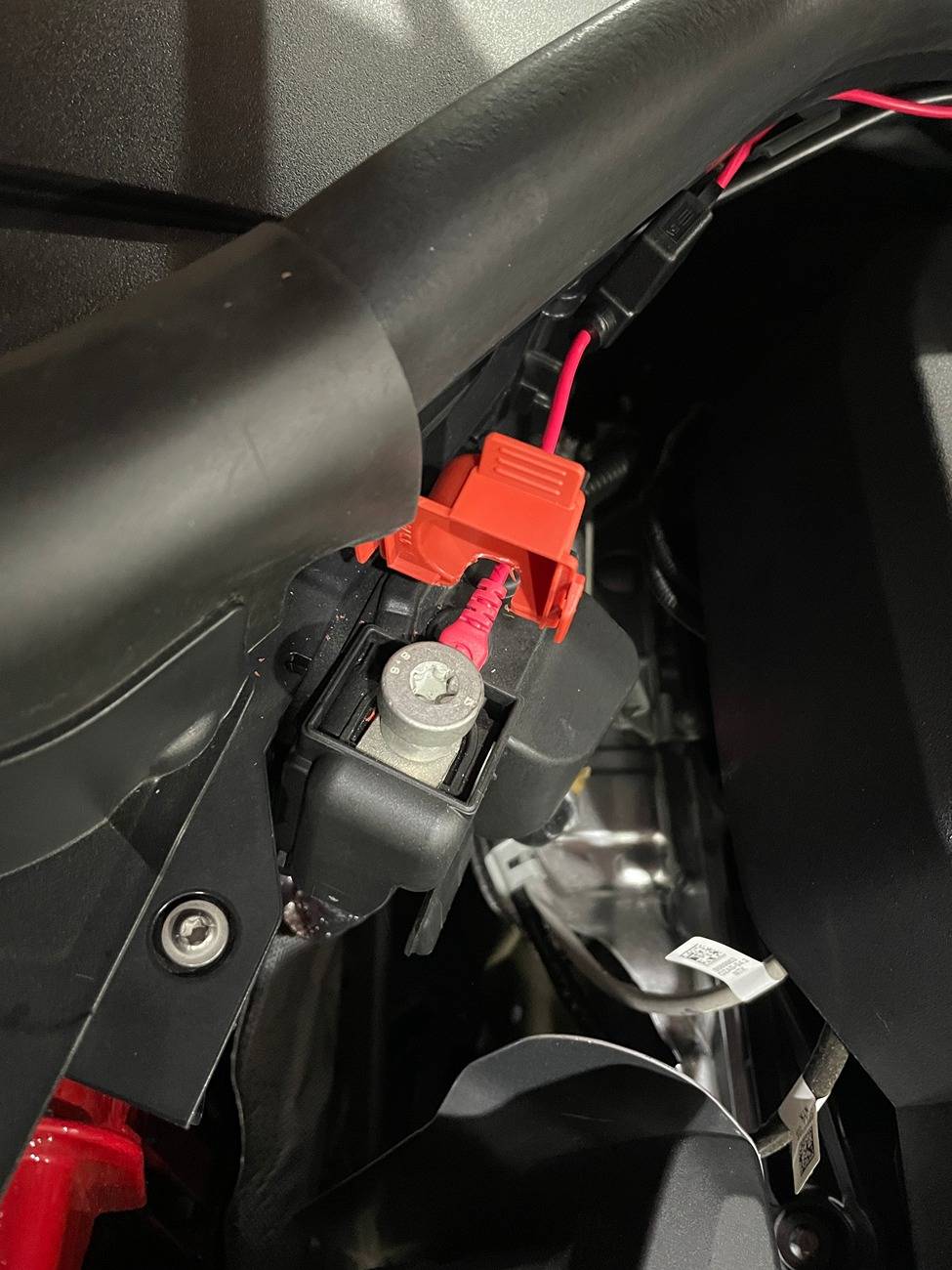
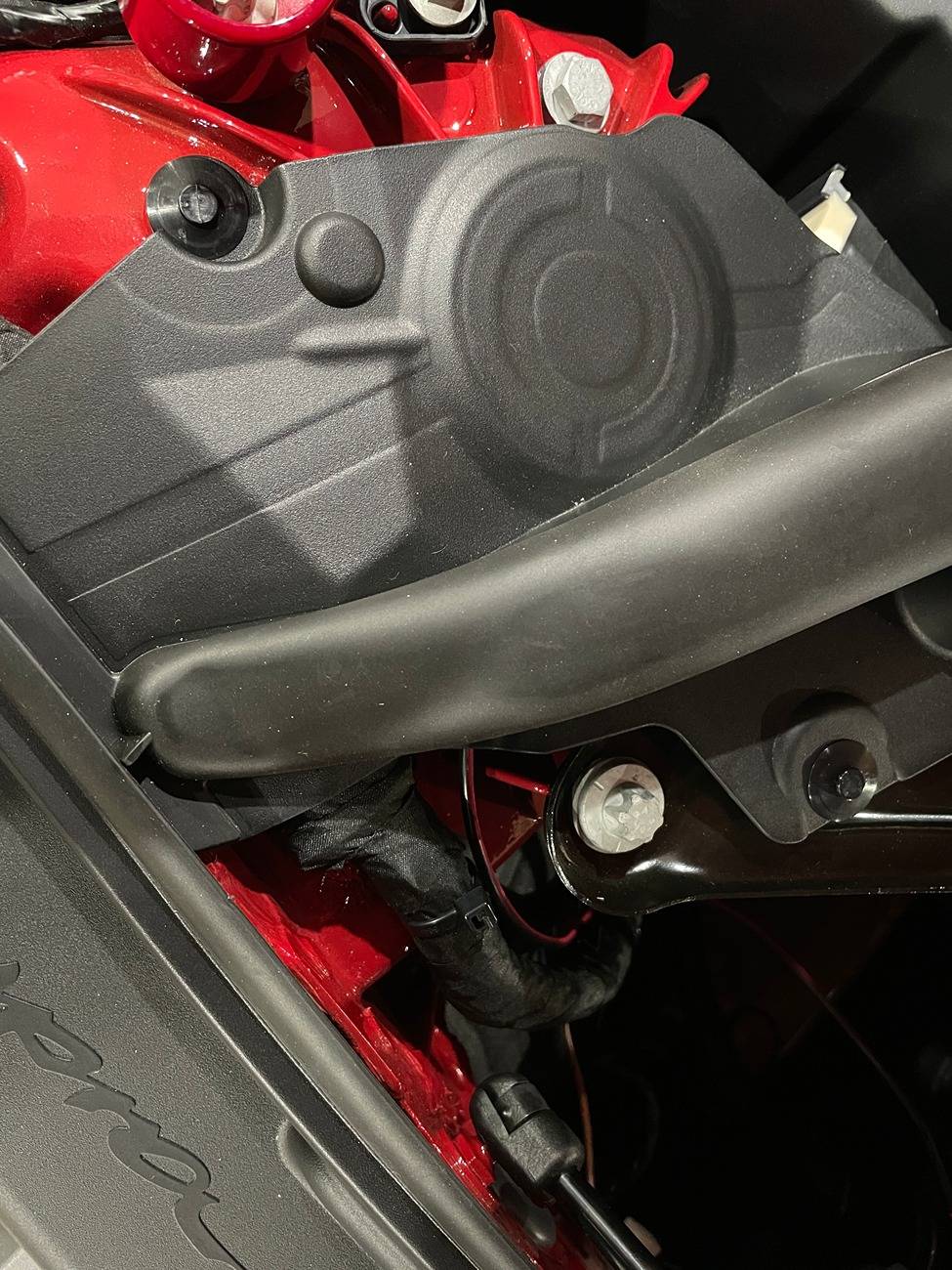
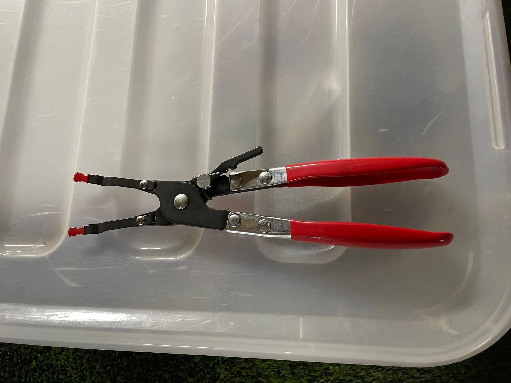
So here's some images of a RHD car. Yours should be neater with less wiring. Use some 3M VHB 5952 tape to attach the unit then run the wires through the slots in the plastic skuttle cover and into the void under the quick release cover. Drill a 8mm hole through the plastic panel shown and run the wires under the chassis brace not over as I have done. It's not really a rubbing issue but under is what I wanted to do but got focused on the job I hate the most that is soldering loose wires together and forgot to run the wires under the brace. Make the soldered joints inside the cubby hole or you can use connectors or those soldering heat shrink sleeves which I've not had success with in the past, possibly because I've used cheap ebay ones. I must try some name brand ones. Maybe the LHD cars have an opening here somewhere and you can avoid drilling the hole. Now I have a tool to hold loose wires while I solder them I'll redo the wiring joint and run it under the brace. I've included an image of the tool and it's great to use and cheap on the Bay or Amazon. Clip the stripped wires into the spring loaded tongs and squeeze the bared ends together with the pliers as the strands intermesh and the pliers lock at that point and hold the wire ends securely as you solder. Then remove the pliers.Yeah, would love to see images to help guide me - thanks in advance!
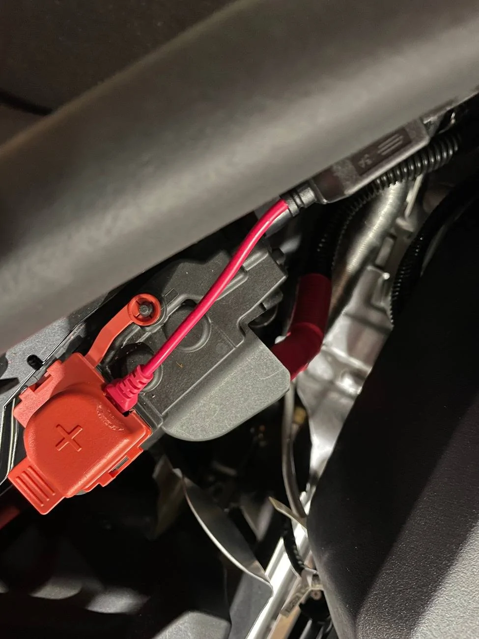
Attach the red to the hot terminal and the black to a strut mount bolt under the plastic cover or another convenient chassis point that provides a good earth. Remove the hot clip on cover and notch it out to clear the terminal so it clips on as normal. I used some split loom cover mesh but thats optional. The cubby hole cover refits no issues as well. I try and avoid as much drilling and modifications as I possibly can with things like this.
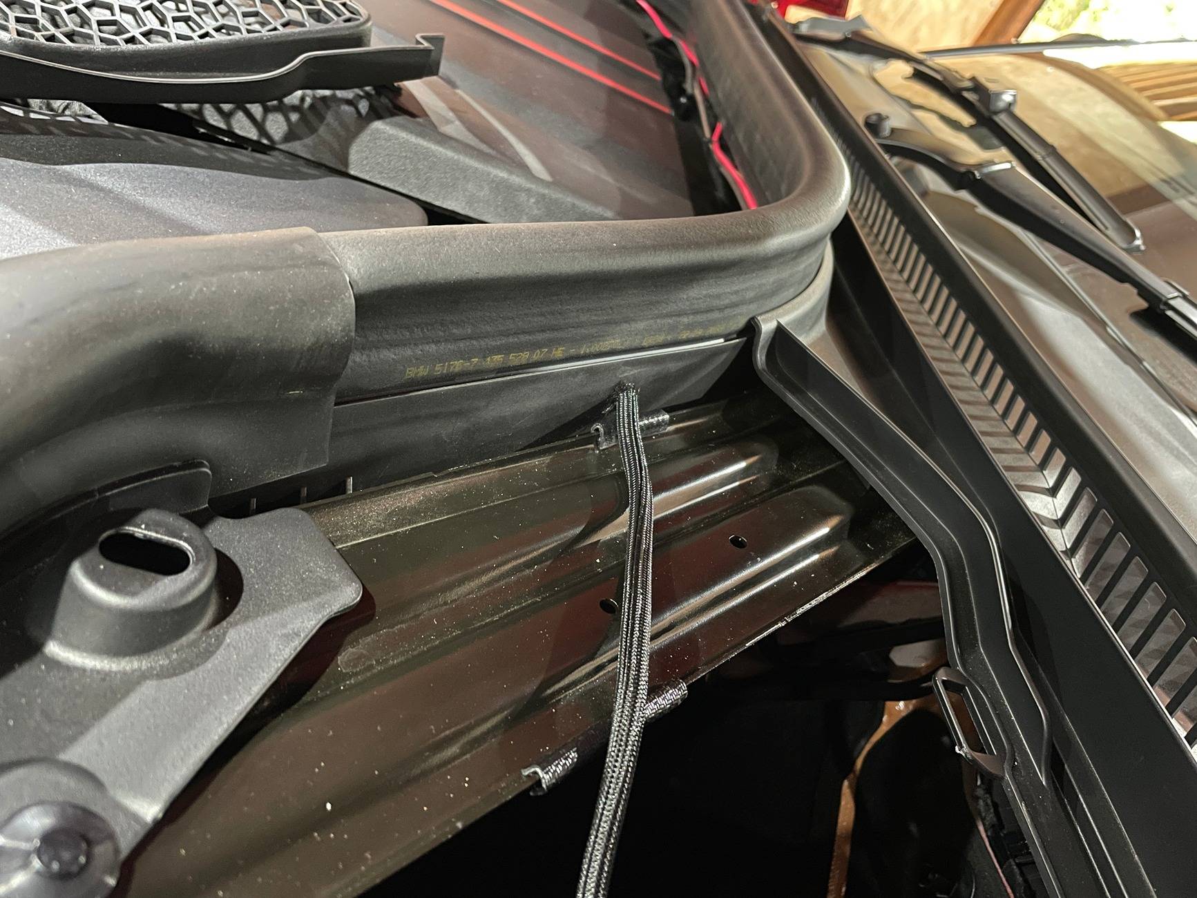
In the 3rd image you can see the negative black wire ( with red stripe from seperating the dual wires) running under the strut cover to the earth point on the strut mount bolt. This cover needs to be removed via the 2 plastic pin retainers.
Kiiro
Member
Brilliant, thank you so much! Really appreciate the comprehensive instructions! I'll have a go at this when I have some time.So here's some images of a RHD car. Yours should be neater with less wiring. Use some 3M VHB 5952 tape to attach the unit then run the wires through the slots in the plastic skuttle cover and into the void under the quick release cover. Drill a 8mm hole through the plastic panel shown and run the wires under the chassis brace not over as I have done. It's not really a rubbing issue but under is what I wanted to do but got focused on the job I hate the most that is soldering loose wires together and forgot to run the wires under the brace. Make the soldered joints inside the cubby hole or you can use connectors or those soldering heat shrink sleeves which I've not had success with in the past, possibly because I've used cheap ebay ones. I must try some name brand ones. Maybe the LHD cars have an opening here somewhere and you can avoid drilling the hole. Now I have a tool to hold loose wires while I solder them I'll redo the wiring joint and run it under the brace. I've included an image of the tool and it's great to use and cheap on the Bay or Amazon. Clip the stripped wires into the spring loaded tongs and squeeze the bared ends together with the pliers as the strands intermesh and the pliers lock at that point and hold the wire ends securely as you solder. Then remove the pliers.
Attach the red to the hot terminal and the black to a strut mount bolt under the plastic cover or another convenient chassis point that provides a good earth. Remove the hot clip on cover and notch it out to clear the terminal so it clips on as normal. I used some split loom cover mesh but thats optional. The cubby hole cover refits no issues as well. I try and avoid as much drilling and modifications as I possibly can with things like this.
In the 3rd image you can see the negative black wire ( with red stripe from seperating the dual wires) running under the strut cover to the earth point on the strut mount bolt. This cover needs to be removed via the 2 plastic pin retainers.
Rocksandblues
Well-Known Member
I rotated my tow hooks today.
FLtrackdays
Well-Known Member
I didn’t even know that was a thang. Shit…. Now I‘m going to have to go buy a second one ?I rotated my tow hooks today.
Edit: Dammit, I was kidding then went looking for a flexible one, since the nail polish is wearing off mine anyway ?
https://x-ph.com/fall-line-motorsports-a90-supra-tow-strap
Last edited:
BrodoFratgins
Well-Known Member
- First Name
- Will
- Joined
- Feb 8, 2023
- Threads
- 8
- Messages
- 189
- Reaction score
- 410
- Location
- Florence, AL
- Car(s)
- 2023 MKV Supra MT
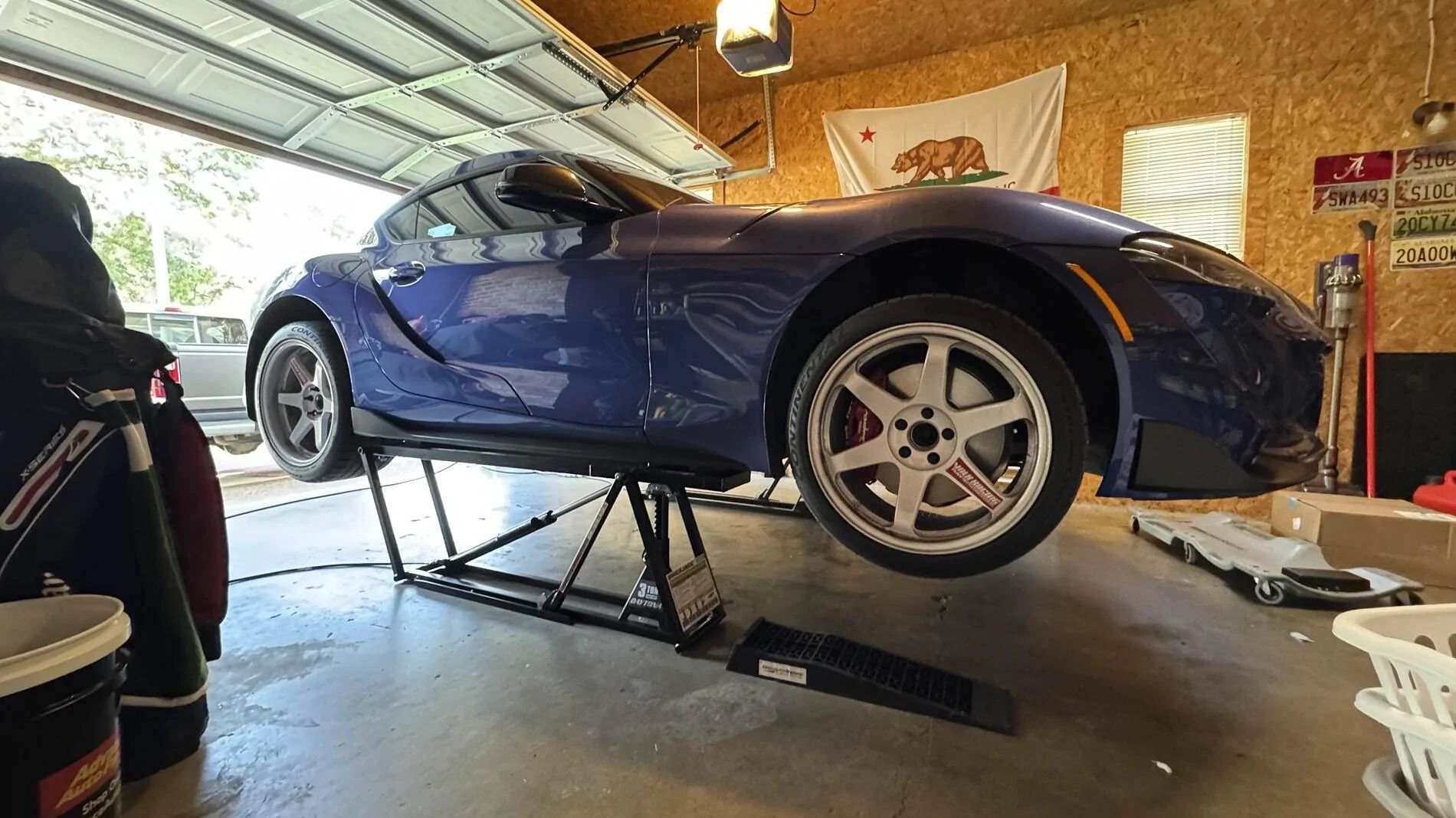
Did the CDV delete and finally really tried out the QuickJacks

Rensuhlo
Well-Known Member
Going to talk about how you broke them?Did the CDV delete and finally really tried out the QuickJacks
PowerGetter
Well-Known Member
- First Name
- Randall
- Joined
- Feb 26, 2024
- Threads
- 14
- Messages
- 285
- Reaction score
- 575
- Location
- Long Beach, California
- Car(s)
- 24' Supra 3.0 MT... the Orange one
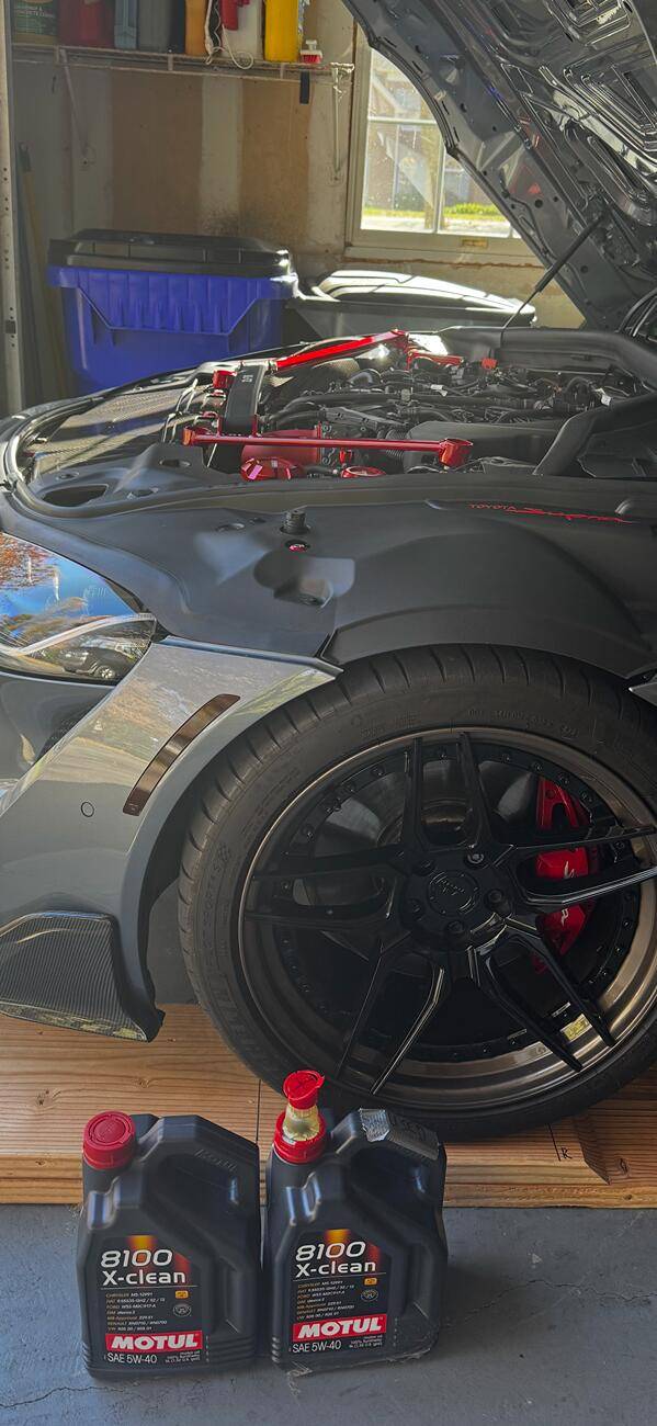
Which fender vents/louvers are you running?Did some autoX
Also grabbed new Endplates from Verus

Rensuhlo
Well-Known Member
Designed and printed by my homie @rwenseWhich fender vents/louvers are you running?
https://www.supramkv.com/threads/fully-3d-printed-fender-vents.21907/
Syeeee
Well-Known Member
Guy in an Altima was staring at it with his mouth hanging open. My first thought was:

“More than your credit score can afford, pal.”

Letting an Altima near you.
chrisriker
Active Member
- First Name
- Chris
- Joined
- Nov 21, 2023
- Threads
- 4
- Messages
- 25
- Reaction score
- 27
- Location
- Connecticut
- Car(s)
- 2020 RAV4, 2025 GR Supra
Got accosted by a drunk man in a cracker barrel parking lot for driving a car with a BMW engine in it
3TMagnetMan
Well-Known Member
- Joined
- Jun 2, 2021
- Threads
- 4
- Messages
- 537
- Reaction score
- 622
- Location
- New Jersey
- Car(s)
- 2021 Supra 3.0 premium
I drove it today 
Erty
Well-Known Member
- First Name
- Eddie
- Joined
- Jul 11, 2022
- Threads
- 4
- Messages
- 287
- Reaction score
- 498
- Location
- Los Angeles, CA
- Car(s)
- '24 Supra 3.0 Premium MT
SameI drove it today
J29DB03
Well-Known Member
Cracker Barrel doesn’t even sell alcohol. How does one get to that point in their life?Got accosted by a drunk man in a cracker barrel parking lot for driving a car with a BMW engine in it
Similar threads
- Replies
- 11
- Views
- 2,942

- Replies
- 34
- Views
- 14,265