Sponsored

Designing FT-1 inspired wing- Looking to see if there is demand as well as suggestions for improvement

OP
OP
TheMaker

TheMaker

Well-Known Member
First Name
Cristian
Joined
Jan 30, 2026
Threads
1
Messages
81
Reaction score
64
Location
Toronto ON
Car(s)
Mazda CX-5
@Strych9, I heard youre the guy to get some input from? Let me know what you think.

@rwense havent heard from you in a little while, let me know your thoughts as well


Im starting the CFD process, so nows the time for suggestions
Sponsored

 
OP
OP
TheMaker

TheMaker

Well-Known Member
First Name
Cristian
Joined
Jan 30, 2026
Threads
1
Messages
81
Reaction score
64
Location
Toronto ON
Car(s)
Mazda CX-5
First CFD test done!

Theres a few things i learned from this but before i get into that here are the results:
Downforce @ 144kmph (90 mph) 140lbs (105 lbs once you cancel out lift produced without the wing)
Drag: 250lbs ***

the plus side is OpenFoam is working and I can finally do successful testing and we do downforce being produced..

Downside is the fact that this test was unreliable.
I need to do a test without the wing and subtract whatever drag is produced from that test because the STL I bought is not 100% watertight despite repairing as much as possible AND it includes the interior, ill need to buy a shell STL only. The test was only 87K cells, normal cell count for a quality test is around 1+ million. That 250lbs drag is total drag, not drag produced by the wing, so i need to do the wingless test to know what is added vs existing ***

So.. we have 140 lbs DF, but not ideal STL, lower cell count (test) and generally not reliable drag data*** but this a good first step. Ill update this post once i do the test without the wing. Ill also do a few more runs and tweak some settings and optimize the simulation parameters and try get better quality data.

Im also considering a built in 6mm tall gurney. So itll fun to see how that affects the results

After that, i align the mounting holes and do a test fit, ill look into an engineering firm to give me solid numbers but so far this is great progress.

***UPDATE***
Car alone is 230 lbs of Drag. the wing add 140 lbs of DF but only 20 lbs of drag

The Design looks solid for the time being...

Screenshot 2026-03-29 183128.webp


Screenshot 2026-03-29 183140.webp
 
Last edited:

Bug2th

Well-Known Member
First Name
Rich
Joined
Jan 27, 2023
Threads
17
Messages
321
Reaction score
243
Location
Folsom, Ca
Car(s)
A91-CF AZ, 1998 GSX
We need an active system for track that adjusts based off steering angle and speed. A dc controlled pump, couple hydraulic struts, get info from car and algorithm to adjust angle would be pretty slick.
 
OP
OP
TheMaker

TheMaker

Well-Known Member
First Name
Cristian
Joined
Jan 30, 2026
Threads
1
Messages
81
Reaction score
64
Location
Toronto ON
Car(s)
Mazda CX-5
We need an active system for track that adjusts based off steering angle and speed. A dc controlled pump, couple hydraulic struts, get info from car and algorithm to adjust angle would be pretty slick.
Its been a crazy little thought in my head to do a DRS active wing based on inputs and manual user settings... but thats leagues higher than where im currently at.
A diffuser is likely next but i need to focus on this for the time being
 
Last edited:

i3igpete

Well-Known Member
Joined
May 16, 2022
Threads
44
Messages
1,257
Reaction score
1,491
Location
Chicago
Car(s)
2023 3.0L 8AT
In general, i would avoid making CFD claims that you have run yourself, unless you have a academic/professional background in it. You will get torn apart by real aero experts (which I am not).

CFD analysis is typically done in steps.
1. Standalone wing. Use a wing with a lot of published data ike s1223, make sure this matches the published papers.
2. DrivAer open source reference model, match the different reference conditions. These first two steps should be as close as possible, because there are other published calibrations you can compare to. Changes to your cfd settings should be carried back to Step 1 to make sure that those results remain consistent.
3. Supra model, does it match toyota published cd? This one might be a bit off because we know that manufacturers like the cherry pick the condition to a publish this number.
4. Then do the car+wing downforce calculation.
5. The difficulty of 2,3,4 is why a lot of wing cfd is done free stream. Because if your car model is garbage, then it'll make your wing result garbage as well. Whereas free stream wing data has less variables to pollute it.

That being said, 140 lb @ 90 works out to be 248 @ 120. This seems a bit ambitious to me, given the relatively small wing area.
 
Last edited:
OP
OP
TheMaker

TheMaker

Well-Known Member
First Name
Cristian
Joined
Jan 30, 2026
Threads
1
Messages
81
Reaction score
64
Location
Toronto ON
Car(s)
Mazda CX-5
In general, i would avoid making CFD claims that you have run yourself, unless you have a academic/professional background in it. You will get torn apart by real experts (which i am not).
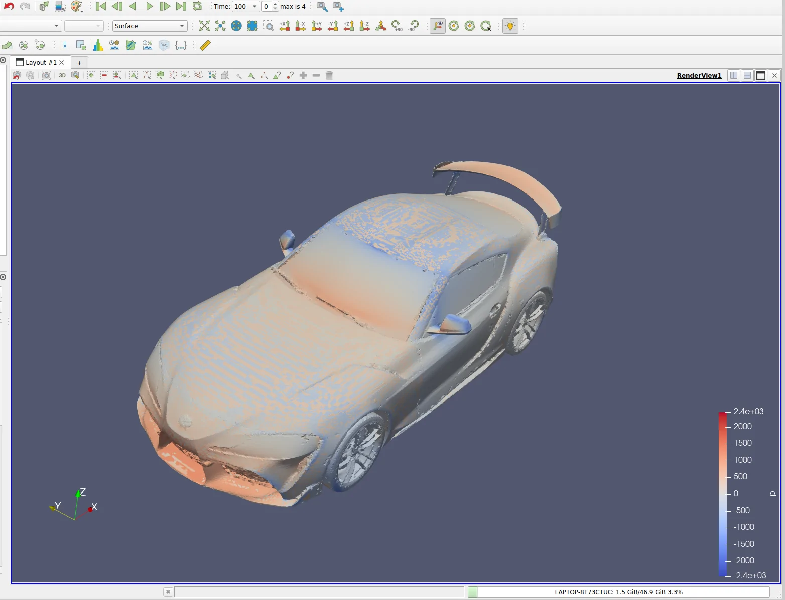
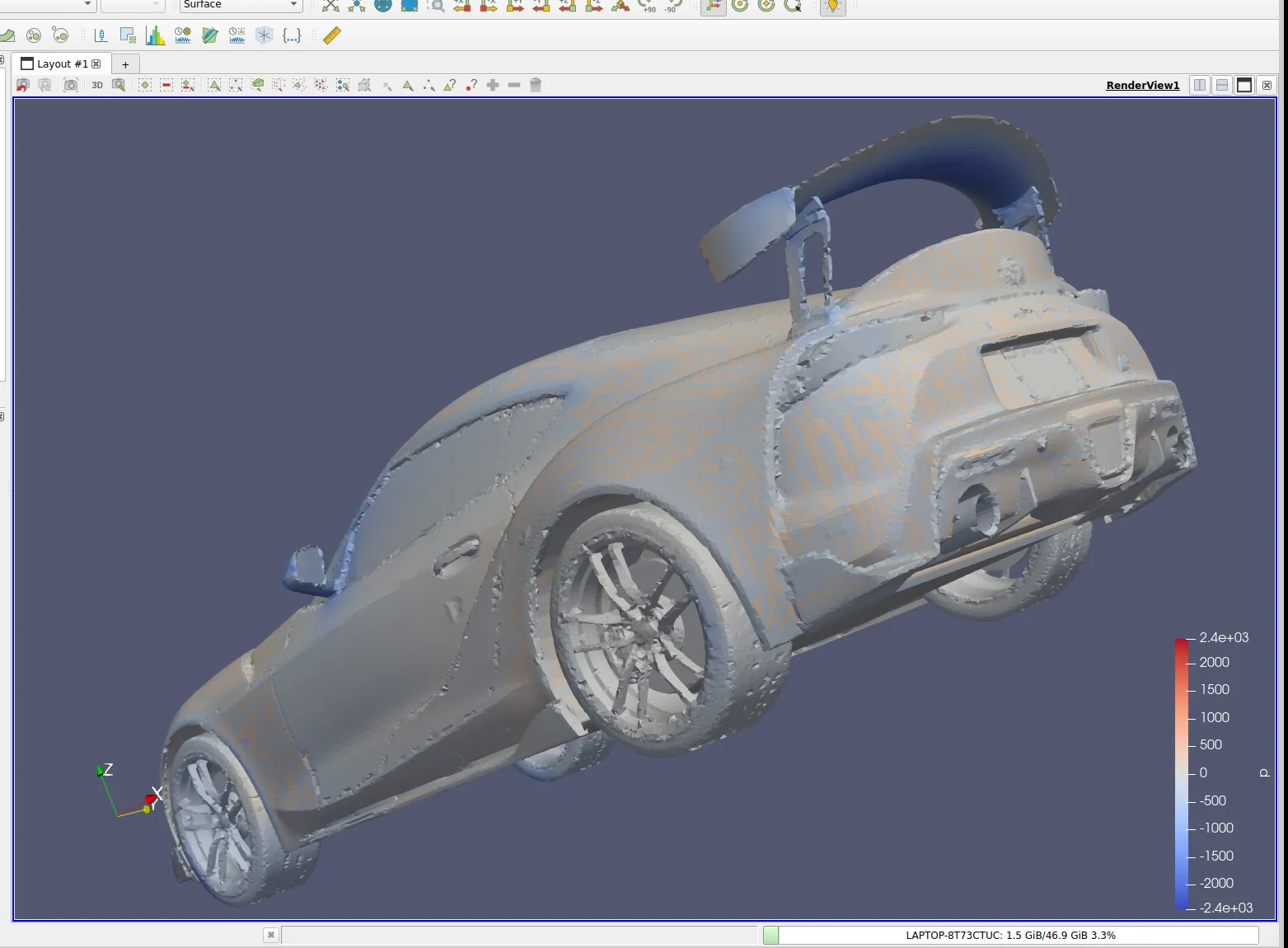
Thats fair enough… i took this simulation as more of an “it seems to work and i didn’t completely waste my time” approach. It was nice to see something that looks like an actual test. There’s some caveats in this case so its not 100% accurate. Im still going to pass this off to an engineering team but its nice to know im heading/designing in the right direction (seemingly)

The 140lbs @90 i agree seems a bit too good to be true. The cell count was only 87k … a 1+ million cell test will be much more accurate. Even if it just neutralizes lift at 60mph/ 100kmph i think that would be a decent result
 
Last edited:

Strych9

Well-Known Member
Joined
Jun 3, 2025
Threads
2
Messages
56
Reaction score
69
Location
Ohio
Car(s)
2021 3.0
I'll be honest, I know enough about CFD to be able to say that @i3igpete knows more about putting CFD to work than I do (post #81). What I know about CFD is mostly just disconnected islands of information and some intuition. I can look at something and get a ballpark idea of what's going on, what probably needs attention, etc. On the other hand, I can make a few contributions when it comes to actual wind tunnel testing in person.

Off the top of my head, I would want that gurney flap at the very trailing edge. Putting it forward by any amount will move the pressure up and forward to behind the flap and trailing edge. You are leaving some gain on the table for the wing area. Beyond that, I'd love to help but I'm just not the guy when it comes to CFD.

As for actually making it, that's well within my scope as motorsports fabricator.

What is your current plan for making it? CF? Printed and painted? Are you still looking at running thru-bolts to attach it to the uprights?

Upright stiffness and good stiffness on at least the top or bottom mount is a big factor. You don't want to run into a problem where the upright bends or where a mount bends or you'll damage the wing or the trunk.

I saw all of this yesterday and forgot to reply. Now I'm fighting a migraine so I can't really get all of my thoughts to text. I'll try to get back on later this evening.
 

Strych9

Well-Known Member
Joined
Jun 3, 2025
Threads
2
Messages
56
Reaction score
69
Location
Ohio
Car(s)
2021 3.0
We need an active system for track that adjusts based off steering angle and speed. A dc controlled pump, couple hydraulic struts, get info from car and algorithm to adjust angle would be pretty slick.
I've gone down the road of designing an active DRS wing. If you're interested, lmk.
 
OP
OP
TheMaker

TheMaker

Well-Known Member
First Name
Cristian
Joined
Jan 30, 2026
Threads
1
Messages
81
Reaction score
64
Location
Toronto ON
Car(s)
Mazda CX-5
I'll be honest, I know enough about CFD to be able to say that @i3igpete knows more about putting CFD to work than I do (post #81). What I know about CFD is mostly just disconnected islands of information and some intuition. I can look at something and get a ballpark idea of what's going on, what probably needs attention, etc. On the other hand, I can make a few contributions when it comes to actual wind tunnel testing in person.

Off the top of my head, I would want that gurney flap at the very trailing edge. Putting it forward by any amount will move the pressure up and forward to behind the flap and trailing edge. You are leaving some gain on the table for the wing area. Beyond that, I'd love to help but I'm just not the guy when it comes to CFD.

As for actually making it, that's well within my scope as motorsports fabricator.

What is your current plan for making it? CF? Printed and painted? Are you still looking at running thru-bolts to attach it to the uprights?

Upright stiffness and good stiffness on at least the top or bottom mount is a big factor. You don't want to run into a problem where the upright bends or where a mount bends or you'll damage the wing or the trunk.

I saw all of this yesterday and forgot to reply. Now I'm fighting a migraine so I can't really get all of my thoughts to text. I'll try to get back on later this evening.
Appreciate the input — especially on the gurney placement, that makes sense putting it right at the trailing edge. I’ll adjust that for the next iteration. I had one in the last iteration built in but i wanted to see how the regular wing would work (also looks cleaner aesthetically imo)


As for construction, current plan is:


• Wing: 3mm composite shell (carbon + fiberglass), reinforced internally with 5–6 spars for stiffness


• Upper mount: 6mm carbon bracket, bonded + riveted into the wing structure

• Risers: 8mm 6061 aluminum

• Lower mount / trunk mount: CNC 6061 aluminum


• Mounting geometry: middle riser hole is angled ~20° or so i can’t quite remember now, to provide cross stiffness


• Underside support: additional aluminum bracing under the trunk for load distribution


Main focus right now is making sure the load path is solid from wing → risers → mounts → chassis so nothing flexes or fatigues over time.


Still dialing in details, but trying to keep it strong, serviceable, and not overly complicated to manufacture.

As for the Cfd, im obviously extremely green when it comes to that stuff but the simplefoam testing definitely can point me in the right direction
 

i3igpete

Well-Known Member
Joined
May 16, 2022
Threads
44
Messages
1,257
Reaction score
1,491
Location
Chicago
Car(s)
2023 3.0L 8AT
Agree with the gurney flap placement, i missed that earlier. though that should be obvious once you run the cfd - the surface pressure would be really low after the gurney, so you might as well cut it off
 
OP
OP
TheMaker

TheMaker

Well-Known Member
First Name
Cristian
Joined
Jan 30, 2026
Threads
1
Messages
81
Reaction score
64
Location
Toronto ON
Car(s)
Mazda CX-5
Agree with the gurney flap placement, i missed that earlier. though that should be obvious once you run the cfd - the surface pressure would be really low after the gurney, so you might as well cut it off
I had a version with one built in but scrapped it because i didn’t like the wing profile. I did a fair but reading up on gurneys and i see how they benefit the performance. This iteration i didn’t make one built in but could add it a separate piece…. Or built in if the general consensus is to include it though that would take away people’s ability to add whatever height they may want

IMG_0982.webp
 

rwense

Well-Known Member
Silver Sponsor
First Name
Evan
Joined
Dec 10, 2021
Threads
45
Messages
711
Reaction score
1,144
Location
Pittsburgh, PA
Car(s)
21 Nitro Yellow A90 Supra, 10 Honda Fit Sport 5spd
Hey!

I apologize, ive been quite busy with travel and prepping my car for the season so I havent been as active.

As far as feedback is concerned, what @i3igpete and @Strych9 Said basically sums up my thoughts. CFD is a good tool for getting a general idea of how things work but I wouldn't put money on the results. Especially when you're dealing with a non-manifold body. But still, its an indicator.

If you want to actually get real hard data, a wind tunnel is your next step. If its something you want to pursue, I can try to get in contact with AJ Hartmann. If I recall, he has some upcoming time at the A2 tunnel. Im not sure where you're located but maybe I can try to arrange either my car or another to test it (although im several hours away lol). The only caveat with the A2 tunnel is it was built for bikes rather than full vehicles, so the data will definitely be much more accurate than CFD but due to the Reynolds number it wont be 100%. I cant remember the cost but I think it was $500/hr?

As for the design, I scrolled through the last few posts, so far its looking great! I like the revision with the endplates. Going to those from the built in endplates that attached to the underside will net some gains just by way of opening up more surface area on the underside of the wing itself. Like others said about the gurney, it should be at the very trailing edge.

Maybe I missed it/misunderstood, but will your mounts work with those of us who have the verus mounts? That might be a pretty cool feature to allow people to not have to re-drill.

Anyway, looking good dude! Im excited to see where it goes 🙂
 

i3igpete

Well-Known Member
Joined
May 16, 2022
Threads
44
Messages
1,257
Reaction score
1,491
Location
Chicago
Car(s)
2023 3.0L 8AT
I believe mario is trying to organize a group trip at the a2 tunnel in the near future as well, on the occams discord.
 
OP
OP
TheMaker

TheMaker

Well-Known Member
First Name
Cristian
Joined
Jan 30, 2026
Threads
1
Messages
81
Reaction score
64
Location
Toronto ON
Car(s)
Mazda CX-5
Hey!

I apologize, ive been quite busy with travel and prepping my car for the season so I havent been as active.

As far as feedback is concerned, what @i3igpete and @Strych9 Said basically sums up my thoughts. CFD is a good tool for getting a general idea of how things work but I wouldn't put money on the results. Especially when you're dealing with a non-manifold body. But still, its an indicator.

If you want to actually get real hard data, a wind tunnel is your next step. If its something you want to pursue, I can try to get in contact with AJ Hartmann. If I recall, he has some upcoming time at the A2 tunnel. Im not sure where you're located but maybe I can try to arrange either my car or another to test it (although im several hours away lol). The only caveat with the A2 tunnel is it was built for bikes rather than full vehicles, so the data will definitely be much more accurate than CFD but due to the Reynolds number it wont be 100%. I cant remember the cost but I think it was $500/hr?

As for the design, I scrolled through the last few posts, so far its looking great! I like the revision with the endplates. Going to those from the built in endplates that attached to the underside will net some gains just by way of opening up more surface area on the underside of the wing itself. Like others said about the gurney, it should be at the very trailing edge.

Maybe I missed it/misunderstood, but will your mounts work with those of us who have the verus mounts? That might be a pretty cool feature to allow people to not have to re-drill.

Anyway, looking good dude! Im excited to see where it goes 🙂
All good man, good luck with the prep and the upcoming season!


From what I’ve gathered with CFD, like you said, it’s just a simulation and results can vary. Now that I’ve figured out how to run it on a personal level, I’ll mainly use it as a tool to help guide design tweaks rather than make any performance claims.


As for the wind tunnel, I never really expected to take it that far. The goal from the start was to create a well-designed street wing with some level of functionality, and I think it’s heading in that direction so far.


For the gurney, that can definitely be added (pretty easily). I wanted to keep the main profile as clean as possible, but a built-in or add-on gurney would help from a functional standpoint if/when I decide to include it.


As for the mounts, I don’t expect most installs will require re-drilling, but I’m not calling out compatibility with any specific setups. The mounting brackets themselves are fully my own design.


I’ll also be including a small printed or fiberglass drill template so installs are straightforward if the holes aren’t already there.
Sponsored


Top