Chappers
Well-Known Member
- First Name
- Greg
- Joined
- Dec 24, 2021
- Threads
- 8
- Messages
- 271
- Reaction score
- 273
- Location
- Birmingham, UK
- Car(s)
- Supra GR 3.0L Tungsten Silver
- Thread starter
- #1
Hi all,
There have been a number of posts of doing this mod by taking the front bumper off, however I wasn't prepared to do that and someone had posted a link to a YouTube video going through the wheel well, so I thought I'd attempt that method, all in it took me just under an hour to complete! and was really easy.
YouTube Video used for reference:
Parts:
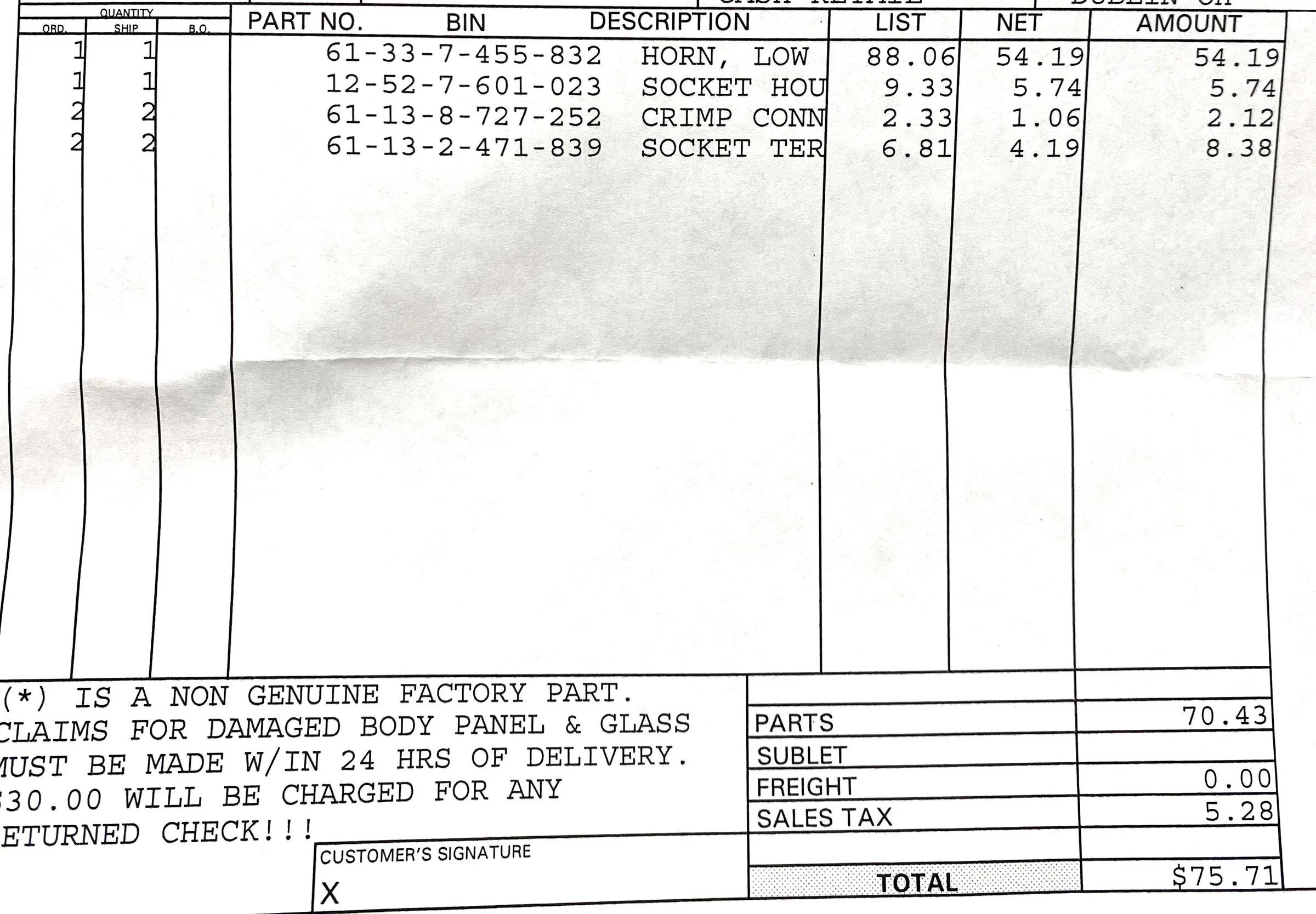
FIAMM 72112 Freeway Blaster LOW Note Horn https://amzn.eu/d/9Z6Wr5Y
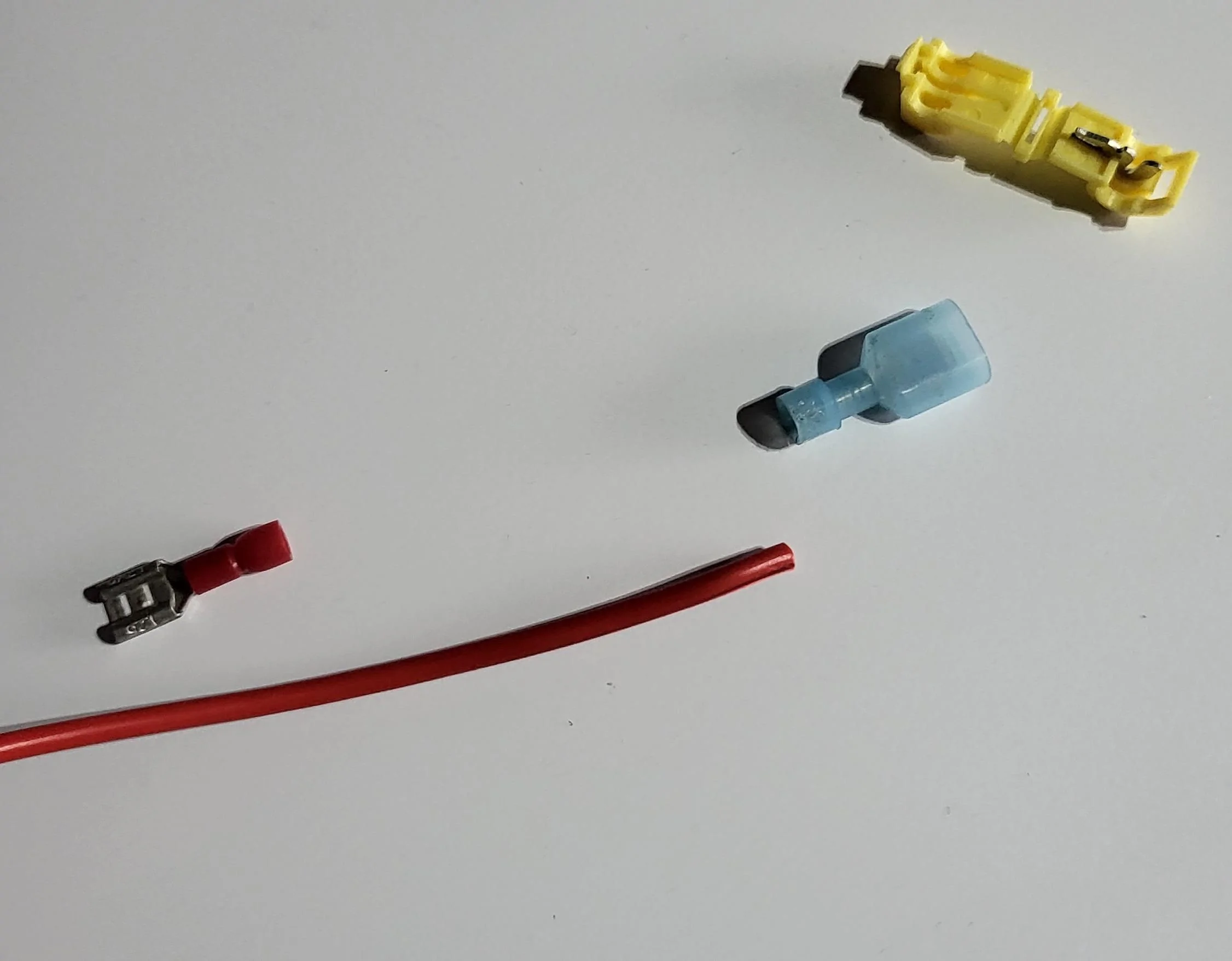
Splice - I had T tap connectors lying around from a previous project, other methods will also work.
Red Wire - I had some wire left over from previous project, suggest going similar CSA size as stock, mine was slightly larger which doesnt matter, just make sure it's not smaller.
Tools:
M8 Socket on a power tool - to save my arm with all the wheel well bolts,
push pin removal tool or flat head screwdriver
Philips screw driver - for single screw type push pin
Torch - not necessary but makes it easier
M13/M15 spanner for high horn bracket
M10 spanner/socket for low horn bracket
crimp tool for spade connector (or pliers)
pliers - aid closing the T tap connector (will probably be needed for other types too, to help cut the insulation on the positive horn wire)

Note: I've just realised that there is a washer on the tray in the image for step 12 I think that originated from the original horn! , I'll be replacing that as soon as I can! I'll try and get more photos and update the process. DOH!!
There have been a number of posts of doing this mod by taking the front bumper off, however I wasn't prepared to do that and someone had posted a link to a YouTube video going through the wheel well, so I thought I'd attempt that method, all in it took me just under an hour to complete! and was really easy.
YouTube Video used for reference:
Parts:
FIAMM 72112 Freeway Blaster LOW Note Horn https://amzn.eu/d/9Z6Wr5Y
Splice - I had T tap connectors lying around from a previous project, other methods will also work.
Red Wire - I had some wire left over from previous project, suggest going similar CSA size as stock, mine was slightly larger which doesnt matter, just make sure it's not smaller.
Tools:
M8 Socket on a power tool - to save my arm with all the wheel well bolts,
push pin removal tool or flat head screwdriver
Philips screw driver - for single screw type push pin
Torch - not necessary but makes it easier
M13/M15 spanner for high horn bracket
M10 spanner/socket for low horn bracket
crimp tool for spade connector (or pliers)
pliers - aid closing the T tap connector (will probably be needed for other types too, to help cut the insulation on the positive horn wire)
- "1st step is to jack up your car" (MCM reference

 )
) - take your front left wheel off
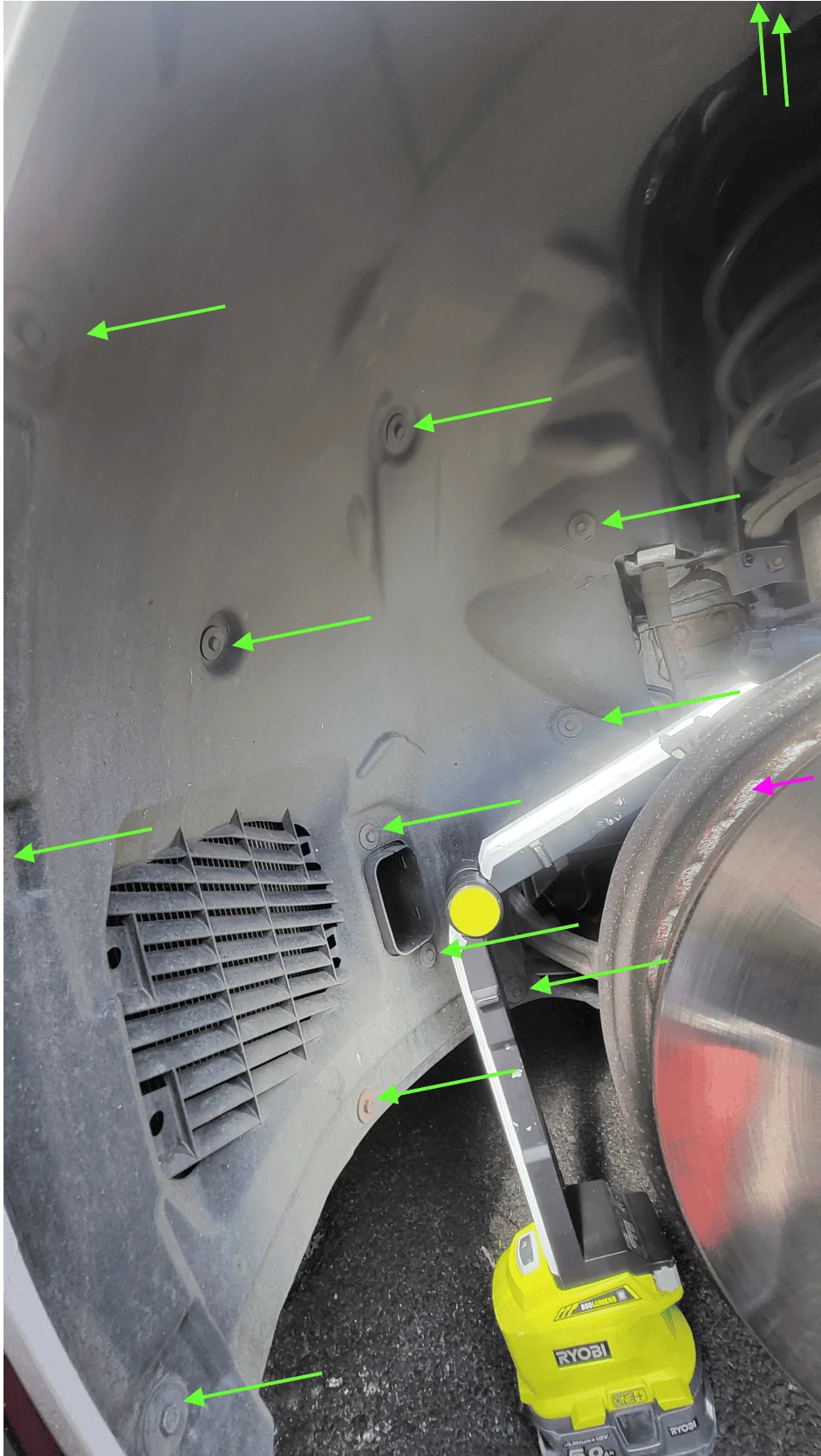
- take the front fender liner off, a lot of M8 bolts and 1 screw type push pin, start at the two at the top where the two liners meet and work your way towards the front .(green M8's, Pink screw type push pin behind brake rotor)

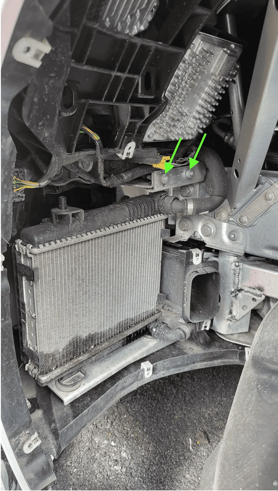
- remove two T45 Torx bolts supporting the heat exchanger, pull forward and pop off the bracket, and tuck away.

- lift up the heat exchanger and rest on the brake rotor
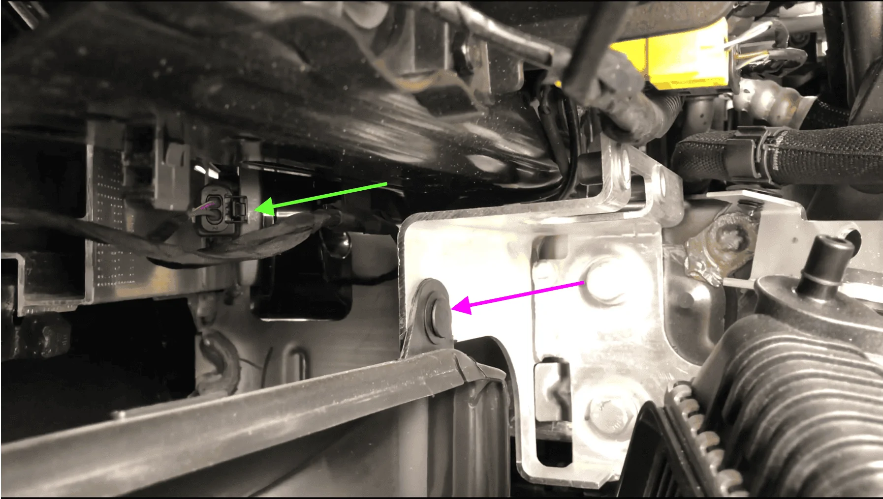
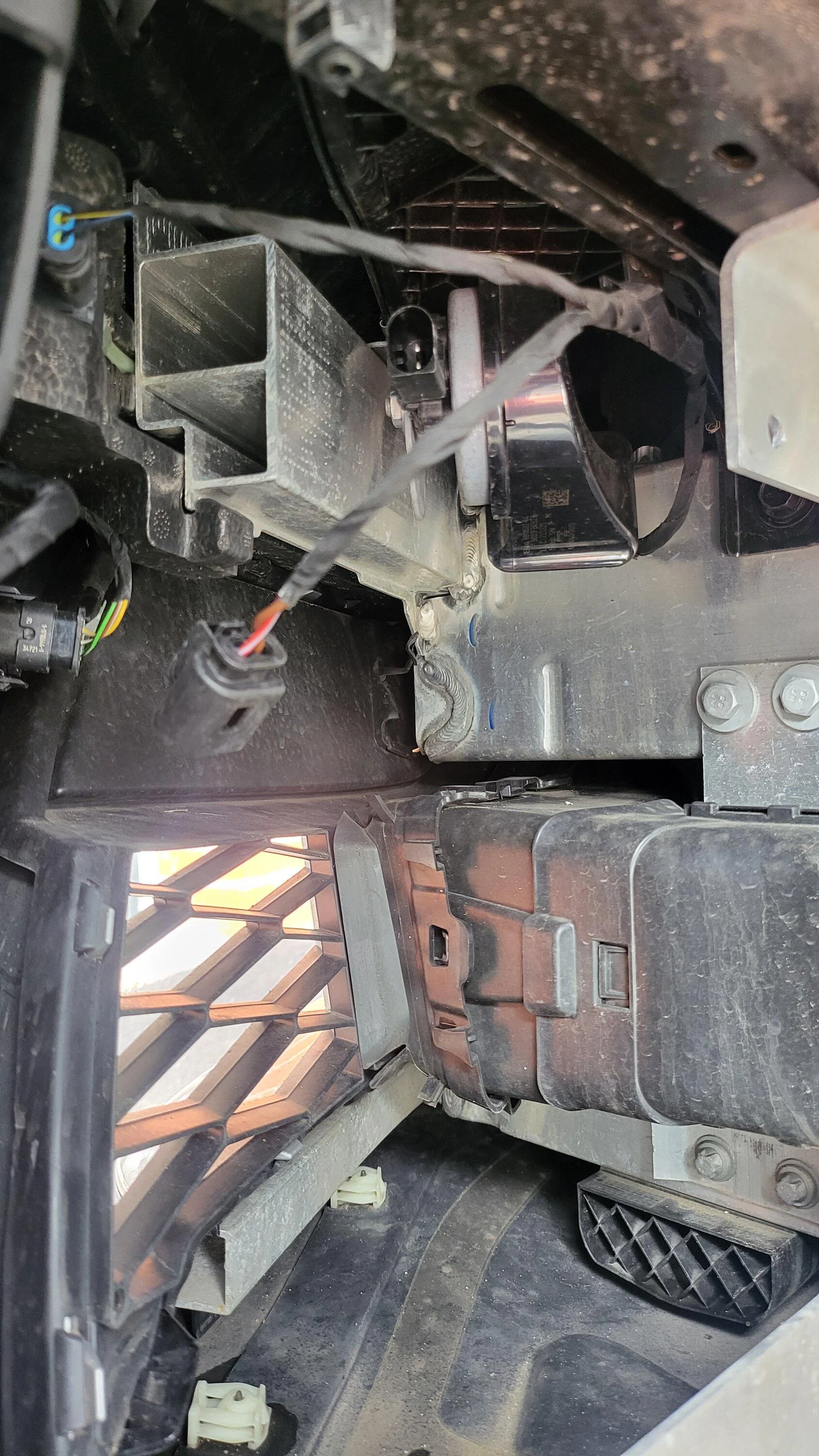
- remove the two push pins holding the duct in place and it should just pull out no effort (1 shown in pink arrow below, the other is at the bottom)
- remove the connector for the horn just a push tab and pull out (Green arrow)

- remove the nut securing the high horn in place.

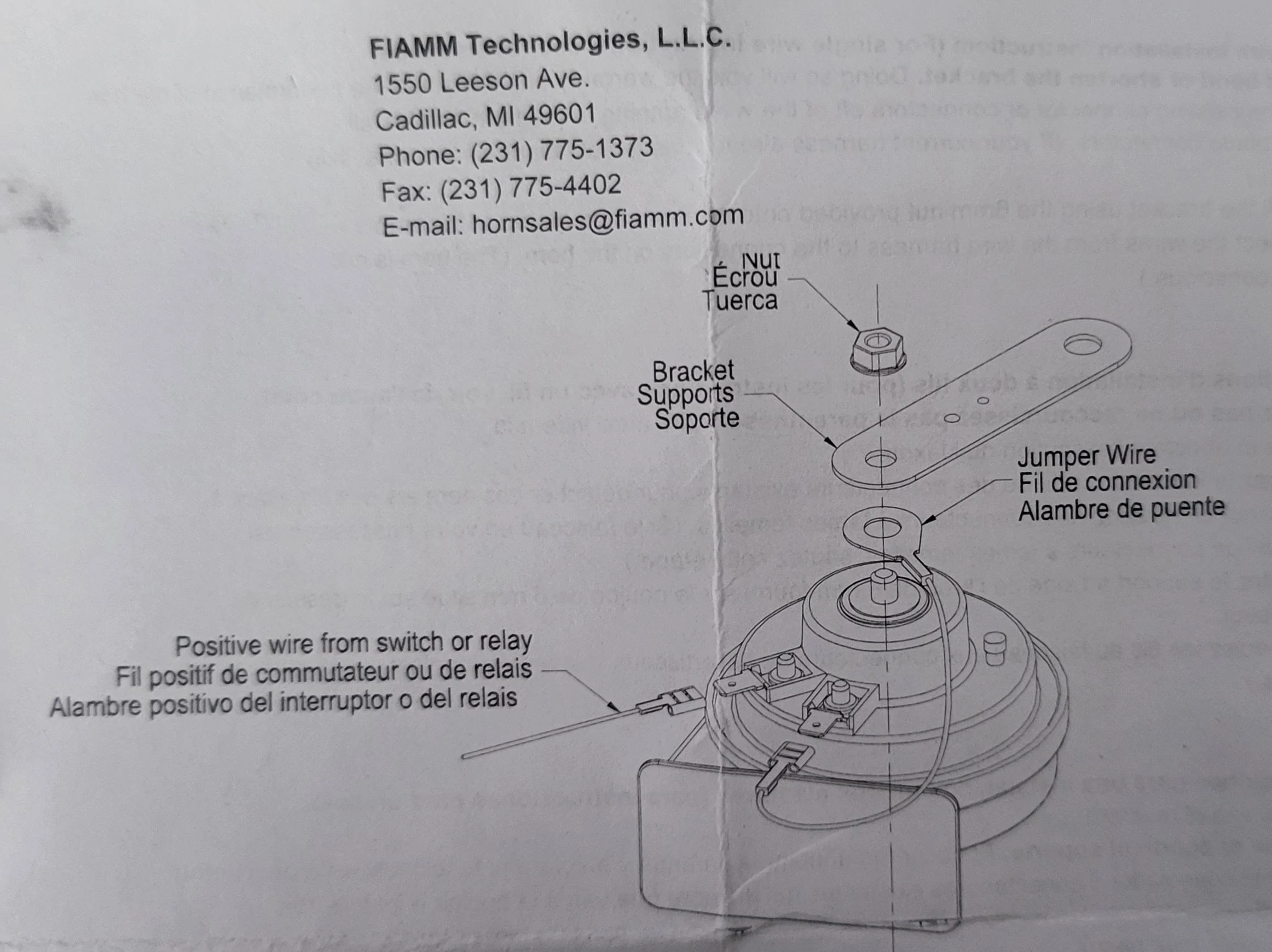
- connect the ground wire to the blade, add the supplied ground loop onto the protruding thread, add the plate that came with it and tighten finger tight to allow to position later. (as per instructions from horn)

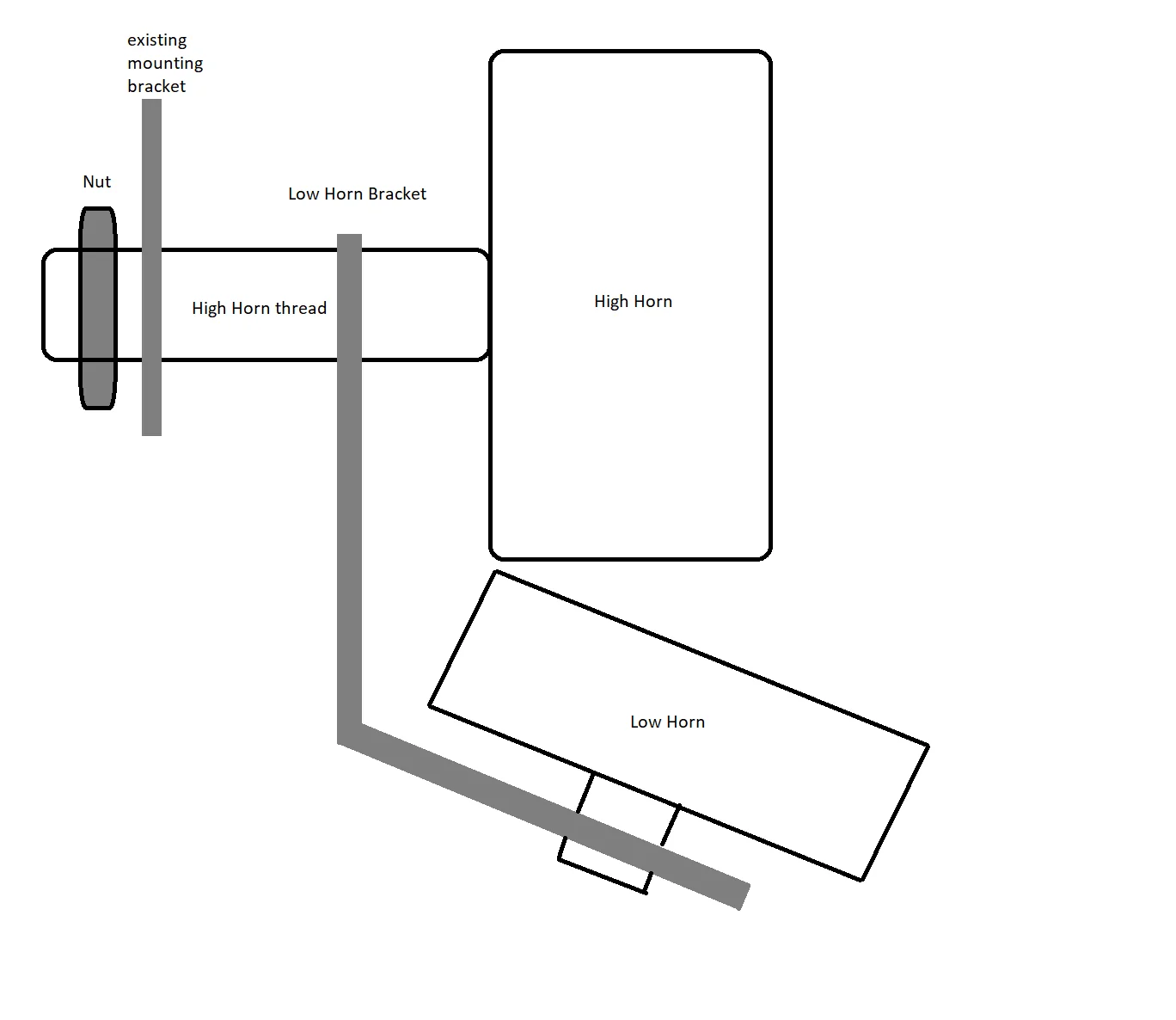
- bend the plate on low horn about 45 degrees (you may need to bend it more so it clears the duct upon reassembly)
- slot the low horn onto high horn protruding thread
- reinstall the high horn with low horn back onto original bracket, this bit is fiddly

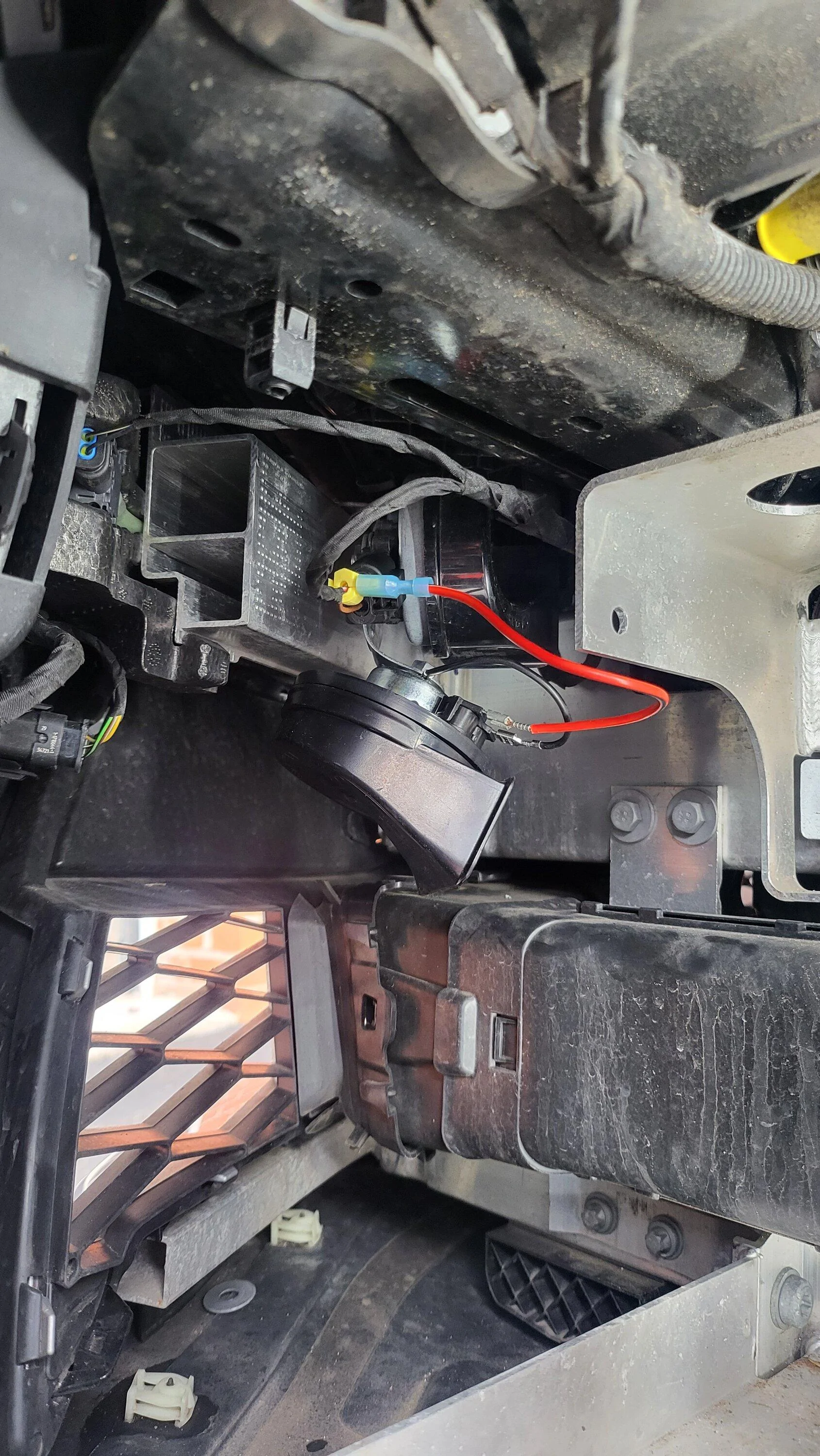
- install splice onto existing positive wire (red) just before the connector.
- prepare positive wire with supplied spade terminal and which ever splicing arrangement you decide.

- (optional) to ensure that the splice was working I used a multimeter on continuity setting to test the connection, I placed one terminal on the horns spade connector and the other on the positive side of the wiring connector, my splice hadn't worked at first so I worked it back and forth to cut the insulation on the wire then it beeped to confirm continuity.
- put the wiring connector back into high horn
- test the horn to make sure it works you should noticeably tell it sounds like a real horn.
- put the car back together in reverse order from step 6.
Note: I've just realised that there is a washer on the tray in the image for step 12 I think that originated from the original horn!
, I'll be replacing that as soon as I can! I'll try and get more photos and update the process. DOH!!Sponsored
Last edited: